
Three-phase resonant converters and planar magnetic integration
Three-phase resonant converters and planar magnetic integration
Topologies, current-balancing control and 1 MHz planar magnetics: the route to ultra-high power density in DC-DC.

Executive summary
Resonant converters are the cornerstone of high-efficiency DC-DC stages in EV fast chargers, server supplies and telecom infrastructure. Their LC resonant network shapes the waveforms to achieve soft switching —ZVS on the primary and ZCS on the secondary rectifiers—, virtually eliminating switching losses and enabling high-frequency operation with smaller passives.
Moving from single-phase to three-phase interleaved with a 120° phase shift naturally cancels the output current ripple through phase superposition, dramatically shrinks the output capacitor filter and spreads thermal losses across the semiconductors. In exchange it triples the magnetic component count and exposes the system to inter-phase current imbalance from manufacturing tolerances (typically ±10 %). This article walks through the topologies (LLC, CLLC, LCC, SRC), the balancing strategies (floating star, CPAB), hybrid PFM+PSM modulation, and the planar magnetic integration that —together with AlN conductive cooling— enables 1 MHz operation at ultra-high power density.
Prototype and improvement figures are traced to the peer-reviewed literature listed at the end; material properties to public literature. Where a figure lacks verifiable backing, it is explicitly flagged as pending source confirmation.
Why three-phase: 120° ripple cancellation
Single-phase resonant converters perform well at low power but exhibit high output current ripple that subjects the filter capacitors to severe thermal and ripple-current stress, forcing them to be oversized. The three-phase interleaved structure removes this bottleneck: operating the three legs with a 120° phase shift between gating signals, the sum of the phase-shifted rectified currents yields an almost continuous power flow with very low residual ripple. The immediate effect is a drastic reduction in the size and capacitance of the output filter, with the corresponding gain in power density and better thermal distribution across the semiconductors.
The schematic below places the full conversion chain and anticipates where power density is won: the integrated planar magnetic core.
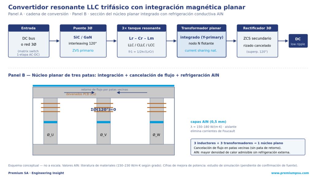
Three-phase resonant network topologies
The dominant high-frequency topologies are LLC, CLLC and LCC, each with a distinct gain, impedance and bidirectional profile. In the LLC, each phase integrates a series resonant inductor (Lr), a series capacitor (Cr) and the transformer’s parallel magnetizing inductance (Lm); below the resonant frequency, Lm participates and provides a boost capability. The resonant frequencies are governed by fr1 = 1/(2π·√(Lr·Cr)) and fr2 = 1/(2π·√((Lr+Lm)·Cr)), and the inductance ratio is m = Lm/Lr; operating fs near fr1, the converter reaches its peak-efficiency point with unity gain.
Table 1 — Comparison of resonant topologies (traced to literature).
| Topology | Soft switching | Bidirectionality | Gain range | Typical application |
|---|---|---|---|---|
| LLC | Full primary ZVS; secondary ZCS below resonance | Asymmetrical; high reactive current in reverse | Moderate; strongly load-dependent far from resonance | Unidirectional EV chargers, server/telecom PSU |
| CLLC | Symmetrical ZVS in both power-flow directions | Completely symmetrical (dual tanks) | Wide; optimized for variable battery voltage | Bidirectional EV chargers, V2G interfaces |
| LCC | ZVS over a wide range down to zero load | Asymmetrical (Cp alters reverse gain) | Exceptionally wide; excellent at light load | High voltage, capacitor charging, wide-range adapters |
| SRC | Primary ZVS above resonance | Symmetrical | Narrow; gain strictly bounded below unity | Fixed-ratio DC-DC, narrow-range bus converters |
On the primary connection, the delta option (Δ-Cr) reduces the tank current by a factor of √3 —cutting the winding copper loss to one third versus the parallel star— but imposes a penalty: the volt-second stress on the high-frequency transformer also rises by √3.
Floating star (Y-primary) and natural current sharing
The most common configuration connects the three transformer primaries in a star with a common floating neutral point. This connection dynamically modulates the neutral-node voltage, reshaping the resonant currents toward a more rectangular than sinusoidal waveform: by flattening the peaks, it lowers the peak and RMS current versus a single-phase converter of equal power, reducing conduction losses. More importantly, it provides a natural current-balancing capability far superior to independent parallel converters.
Self-compensation and MTBF. Under resonant-capacitor tolerance or degradation (a common failure mode in high-temperature environments), the floating neutral shifts dynamically to accommodate the drift, preventing localized thermal runaway on an ageing phase. This passive, zero-cost balancing limits the mean current mismatch to under 15 % without any active control, and extends system MTBF.
Current imbalance and active mitigation
Despite the star node’s natural balancing, passive-component manufacturing tolerances (typically ±10 %) shift each phase’s impedance and produce thermal asymmetry and extra output-capacitor ripple. Hardware solutions (balancing transformers) add loss and volume, so active control is preferred:
- CPAB (Current Phase Angle Balancing): directly regulates the phase angles of the resonant currents with dedicated PI loops to hold an exact 120° spatial displacement, limiting residual mismatch to under 5 % even under severe tolerances. It outperforms the historical TCB (Trigonometric Current Balancing), which has poor transient response.
- RMS-based real-time algorithm: measures the individual RMS currents and linearly adjusts the input-voltage phase shifts (V and W channels relative to the U reference), reducing the imbalance factor to under 2 % across the full frequency range.
- Phase-Shift Modulation (PSM): in two-module parallel three-phase structures, PFM regulates voltage and PSM shares current; a 30° displacement between modules minimizes total output ripple.
Stable implementation demands careful loop design: in a reference application, the voltage loop (PFM) uses a PI compensator with a 5 kHz crossover and 96° phase margin, while the current-sharing loop (PSM) uses integral compensators with a lower 500 Hz crossover and 91° margin to avoid loop interaction. With a physical mismatch of LrA=20 µH and LrB=16 µH, without active sharing the phase shifts lock at an identical 40.5°; with PSM active the controller dynamically diverges them (41.8° and 39.2°) and restores current symmetry.
Hybrid PFM + PSM modulation
Conventional PFM control varies the switching frequency to regulate voltage, but very wide voltage ranges (an EV charger may span 200 V to 1000 V) force it to sweep a huge frequency spectrum, complicating the EMI filter, drivers and magnetics, and increasing circulating-current losses far from resonance. The hybrid scheme uses PFM below resonance (boost mode, high efficiency) and activates PFM+PSM above it: shifting the phase angle between legs generates a three-level voltage waveform that adjusts the tank’s effective excitation, minimizing the frequency range and reactive circulating energy. The VCR-based VFSHC variant switches modes without transients and completely eliminates the «inoperative region» of conventional hybrid schemes.
Planar magnetic integration: three in one
The main drawback of three-phase is the escalation of magnetic components: three independent inductors and three transformers raise volume, cost and assembly complexity. Planar integration merges them into a single structure. Splitting the primaries across the legs of a three-column core, the sum of the 120°-shifted fluxes cancels in the center leg, which dramatically reduces core losses and simplifies thermal management. With WBG semiconductors (SiC/GaN) the frequency rises to the 500 kHz–1 MHz+ range, enabling PCB copper windings and very low-profile planar cores.
Not all geometries are equal. The classic square integrated core suffers asymmetrical reluctance paths —the center leg is shorter than the outer ones— which induce phase imbalance. An elegant spatial solution is the cylindrical planar core, which enforces complete three-dimensional symmetry and aligns the reluctances of the three phases. For very high currents, the matrix transformer (series primaries, parallel secondaries) distributes voltage stress and heat dissipation.
Table 2 — Planar magnetic integration strategies (traced to literature).
| Strategy | Core complexity | HF loss reduction | Reluctance symmetry | Engineering challenge |
|---|---|---|---|---|
| Discrete parallel cores | Low (standard cores) | Low (no flux cancellation) | High (independent paths) | Large volume, low density, high cost |
| Square integrated core | Moderate (single E-core) | Moderate (center-leg cancellation) | Low (outer legs longer) | Asymmetry → phase imbalance |
| Cylindrical symmetrical core | High (custom geometry) | High (optimized uniform flux) | High (complete 3D symmetry) | Custom manufacturing and winding |
| Matrix transformer | High (multi-core series-parallel) | High (distributed core volume) | High (symmetrical PCB routing) | High secondary leakage inductance; routing |
Core thermal management at 1 MHz: the role of AlN
As frequency rises to 1 MHz, ferrite core losses grow and push planar components toward their thermal margins. The reflex of inserting a metal piece (copper, aluminium) to cool the transformer internally is counterproductive: the alternating magnetic field induces severe eddy currents in the metal, sending losses up. The solution is a material that conducts heat but insulates electrically: aluminium nitride (AlN).
AlN combines a high thermal conductivity —on the order of 150–180 W/(m·K), and up to 230 W/(m·K) in premium commercial grades, comparable to some metals— with high dielectric strength. It is also 7 to 10 times the thermal conductor of alumina (Al₂O₃, ~30 W/(m·K)), cheap but poor, and unlike beryllium oxide (BeO, ~260 W/(m·K)) it is non-toxic. Being a non-conductive ceramic, interleaving thin AlN plates (e.g., 0.5 mm) within the ferrite block stack creates internal conductive cooling channels without inducing parasitic currents, draining heat from the inner —typically hottest— regions and lowering the core’s peak temperature.
Rigour on the improvement figures. Thermal-optimization studies report that a 1 MHz ferrite core with embedded 0.5 mm AlN layers would admit an increase on the order of 167 % in its admissible heat-generation density (theoretical models in the 173–187 % range), and that dedicating 30 % to 35 % of the core volume to AlN would maximize the sustainable useful flux. These specific figures could not be verified against independent public literature and are carried over as a simulation-study datum pending source confirmation; the AlN material properties are supported by materials literature. Recommendation: validate experimentally before publishing the improvement figures as a closed datum.
WBG semiconductors: the enabler and its constraints
High-frequency operation is made possible by wide-bandgap semiconductors. Versus silicon (Eg 1.1 eV, critical field 0.3 MV/cm, mobility 1400 cm²/V·s), SiC (3.3 eV, 3.0 MV/cm, 900 cm²/V·s, excellent thermal conductivity) and GaN (3.4 eV, 3.3 MV/cm, 2000 cm²/V·s) allow thinner drift regions, lower Rds(on) and blocking voltages from 650 V (lateral GaN) to 1200 V+ (vertical SiC).
The price is demanding hardware design. dv/dt of hundreds of volts per nanosecond excites circuit parasitics, generating oscillations, EMI and instability. In E-mode GaN, with a narrow gate window (−10 V to 7 V) and low threshold (Vth < 2 V), gate crosstalk can trigger catastrophic false turn-on events. The designer must use gate drivers with active Miller clamp, Kelvin source connections and strictly symmetrical PCB layouts to suppress spikes and keep the soft-switching boundaries.
Validated prototypes
Industry has built and measured several platforms that confirm the architecture’s advantages:
Table 3 — Published prototypes (parameters and achievements, traced to literature).
| Platform | Topology | f_sw | Voltage / power | Efficiency and achievement |
|---|---|---|---|---|
| 30 kW EV charger | Three-phase interleaved LLC (SiC) | 135–250 kHz | Vin 650–850 V; Vout 200–1000 V | Peak > 98 %; full load > 97 % |
| 10 kW high-density CLLC | Three-phase CLLC | High frequency | 800 V DC bus | Peak 97.5 %; cylindrical planar; minimal imbalance |
| 500 W single-stage AC-DC | Matrix switch + LLC | 465–547 kHz | Vin 100 V AC; Vout 130 V DC | Peak 97 %; PF 0.99; THD 3.95 % |
| 4 kW bidirectional | Three-phase LCC | High frequency | 320 V ↔ 28 V battery | Peak 92.2 %; range 0–12.5 A / 0–142 A |
| 3.6 kW grid-tied | Interleaved LLC | Synchronous frequency | 48 V output | CPAB controller with verified stable sharing |
Synthesis — Premium SA design criterion
Translated into project recommendations, the three-phase resonant architecture is ordered as follows:
- Bidirectional → CLLC: for V2G and grid storage, CLLC over LLC guarantees symmetrical gain and identical soft-switching boundaries in both directions.
- Passive balancing → floating star: in high power with expected ageing or tolerances, the floating Y node provides zero-cost balancing (<15 %) and drift self-compensation.
- Fine balancing → CPAB software: for critical applications, CPAB alongside the floating node drives the mismatch below 5 % with no extra hardware.
- Wide range → hybrid PFM+PSM (VFSHC): limits the frequency spectrum, optimizes the planar magnetics and avoids the inoperative region.
- Density → planar magnetics + AlN: cylindrical or matrix cores to cancel flux and spread heat; AlN conductive cooling to raise the thermal limit at 1 MHz without inducing eddy currents.
- WBG → disciplined layout: active Miller clamp, Kelvin source and PCB symmetry to tame SiC/GaN dv/dt.
Sources and traceability
Premium SA internal catalogue: block B4 (resonant and multilevel topologies, manual_avanzado_diseno), B8 (passive/magnetic components), B7 (advanced thermal management). Consistent with the Premium article «Multilevel Inverters» v1.0 (no overlap: that one covers the inverter stage; this one, the resonant DC-DC stage).
External technical literature (selection):
- Three-phase architecture and control: studies on three-phase LLC/CLLC/LCC, current sharing, CPAB and hybrid PFM-PSM modulation (IEEE/MDPI/ResearchGate; Wolfspeed 30 kW SiC charger).
- Planar integration: cylindrical symmetrical core and matrix transformers for high-frequency three-phase LLC (MDPI Energies; magnetic-integration thesis, White Rose).
- AlN properties: materials data (Kyocera, Precision Ceramics, substrate manufacturers): λ 150–230 W/(m·K) by grade; alumina ~30 W/(m·K); BeO ~260 W/(m·K), toxic; CTE matched to Si.
- AlN power-improvement figures: simulation study cited in the source material — pending primary-source confirmation before publication as a closed datum.
About Premium SA
Premium SA is a Barcelona-based manufacturer of electronic power converters for railway, industrial and energy applications. With more than 900 standard product designs and over 40 years of operational experience, Premium SA supplies DC/DC converters, DC/AC inverters, AC/AC frequency converters, battery chargers, rectifiers and UPS systems from 50 W to 72 kW.
The D2x / DFR methodology integrates topology, digital control and the magnetic-thermal architecture as coupled decisions from the conceptual phase, with a preference for custom solutions, WBG semiconductors and traceable experimental validation.