• News
  • Resources
  • SHOP
  • EN
    • ES
  • Shopping Cart Shopping Cart
    0Shopping Cart
Premium PSU
  • About us
    • We are Premium
    • Quality
    • Careers
  • Products
    • Standard
      • DC/DC Converters
      • DC/AC Inverters
      • AC/DC Battery chargers
      • AC/AC Variable Frequency Drive
      • AC/DC Rectifiers
      • Product Selector
      • EV Chargers
      • IoT Cloud Solutions
      • AC/DC DIN Rail Power Supplies and Accessories
    • Custom solutions
      • Design your solution
  • Industries
    • High Tech Industry
    • Energy
    • Defense
    • Rail & Transportation
    • Electric Mobility
    • Data Centers
  • Services
  • Case Studies
  • Contact
  • Click to open the search input field Click to open the search input field Search
  • Menu Menu
Home1 / Sin categoría
innotrans
Events and corporate news, Sin categoría

Railway power electronics: technology vectors, standards and design

Railway Power Electronics

Technology vectors, regulatory demands and design response
Premium PSU
·
InnoTrans 2026 · Berlin · 22-25 September · Hall 17, Booth 425
€185 BGlobal rail market 2024-25
€34 BPower-electronics investment 2025-30 (CAGR 6.3%)
70 %New platforms with SiC (2026)
+ 40 yearsin railway power electronics


1. Market in transition: three converging vectors

The global rail market stands at €185 billion per year (2024-25), with a projected 4% CAGR to 2030. Three vectors explain the structural shift: mass electrification — more than 60% of new acquisitions are electric or hybrid, with Europe leading at an 85% electrified network; end-to-end vehicle digitalization — digital twins, IoT predictive maintenance and smart energy management; and reconfiguration of onboard power electronics toward wide-bandgap and distributed modular architectures.

The specific railway power-electronics sub-segment is valued at €11.2 billion globally, with a 6.3% CAGR — clearly above the growth of the parent market. Cumulative investment projected for 2025-2030 reaches €34 billion, with traction converters capturing 58% and auxiliary systems (HVAC, passenger services, chargers) growing rapidly on the back of existing-fleet renewal. Technical specification is converging globally toward EN 50155 as the reference, even in Asia-Pacific and North American markets that traditionally operated under alternative regulatory frameworks.

2. Technology vectors: SiC, MMC, distribution and bidirectionality

Four simultaneous technology leaps are redefining what a railway power-electronics platform must deliver. Each addresses a specific limitation of the previous generation, and all raise the engineering demands placed on the supplier.

SiC as the default semiconductor. Silicon Carbide adoption moves from selective to mainstream: projections indicate SiC will be specified in ~70% of new platforms in 2025-2026. The technical case is built on four simultaneous improvements over silicon IGBT: 97-98% efficiency vs. 92-94%; 30-40% mass reduction through lower thermal dissipation and more compact passives; switching frequencies up to 100 kHz vs. 2-5 kHz for IGBT (70% reduction in inductors and filters); and 175-200 °C operating Tj vs. 125 °C for silicon.

Modular Multilevel Converters (MMC). In high-power traction (6-9 MW) the MMC topology is consolidating as the dominant architecture: 70% reduction in harmonics injected into the catenary, power factor > 0.98, lower stress through voltage distribution across modules. The 25% initial cost premium is amortized through lower maintenance and longer service life. The implication for auxiliary design is indirect but significant: the MMC architecture modifies the catenary’s harmonic spectrum, requiring recalibrated EMC immunity in the auxiliary converters that share that bus.

Distributed architectures. Migration from centralized 200+ kVA systems toward networks of distributed 10-15 kVA inverters per zone. The advantages are operational: fault isolation without affecting the full service, granular per-zone monitoring, optimal sizing to actual load, modular replacement without immobilization. Benefits reported across fleets: 40% cabling reduction and reliability improvement above 35%.

Bidirectionality and digital twins (2027-2030 horizon). Bidirectional converters with energy return to the catenary (regenerative efficiency > 85%) and integration with smart grids for auxiliary services will move from pilot to standard in 2027-2028. In parallel, digital twins with ML for predictive maintenance are reaching fault-detection accuracies of 90-95% with windows of up to 90 days, becoming widespread toward 2029-2030. Platforms acquired in 2026 will operate until 2056: firmware-extensibility toward these capabilities is a selection criterion today.

3. Design implication: from compliance to durability

Adopting SiC, MMC or modular distribution is not a bill-of-materials decision — it is an engineering-process decision. The dominant failure modes in railway power electronics — electrolytic capacitor degradation, electromechanical wear, thermo-mechanical fatigue of solder joints, gate-oxide degradation in SiC under cyclic dV/dt stress — are not mitigated by catalog derating. They require mission-profile quantification, service-life calculation by Physics-of-Failure (PoF) specific to each mechanism, and a qualification discipline that goes beyond the initial type test.

The applicable regulatory stack (EN 50155:2017+A1:2020, EN 50121-3-2 for onboard EMC, EN 45545-2 HL3 for fire safety, EN 61373 Cat. 1A/1B for shock and vibration, EN 50128:2011/A2:2020 for SSIL firmware, EN 50126-1:2017 for RAMS) defines the product floor. The engineering process defines the ceiling. The difference between the two is what determines whether a product still complies with EN 50155 at year 0 or at year 15 in service.

3.1 Applied DFR process: four gates with quantitative exit criteria

Premium PSU applies a four-gate Design for Reliability process to every railway program. D2W (Design to Work): complete schematic, functional simulation, validated topology. D2F (Design to Function): prototype measuring every specified function, EMC and thermal pre-compliance passed. D4R (Design for Reliability): mission profile signed off by the customer, derating verified, FMEA with RPN < 80, PoF service life > target × 3. D4Co (Design for Compliance): complete EN 50155/50121/45545/61373 dossier, FRACAS activated in production. No product enters production without a signed D4Co.

The mission profile is the non-negotiable artifact: maximum and minimum ambient temperature, daily thermal cycles, cyclic humidity, altitude, RMS vibration per axis, number of annual cold starts, frequency of S2 supply-interruption events over the 30-year horizon. Without a validated mission profile there is no defensible MTBF calculation — only an optimistic datasheet.

4. Premium PSU portfolio: response to the complete conversion matrix

Covering all four families (AC/AC, AC/DC, DC/AC, DC/DC) with a single EN 50155-qualified supplier reduces multi-supplier qualification overhead, simplifies TCO, guarantees mechanical and electrical consistency between converters on the same vehicle, and eliminates the grey areas of responsibility in systemic cross-coupling.

Family Reference Power / Input Railway application
DC/AC inverter OVX-6400 6.4 kVA · 600/750 Vdc catenary Direct-catenary auxiliary inverter · 400 Vac 3-ph
DC/AC inverter ODX-3000L 3-4 kVA · 72 Vdc → 400 Vac 3-ph Extended-range 3-ph auxiliary inverter
DC/AC inverter ODS-3000 / OT4 3-4 kVA · EN 50155 OT2/OT4 (-40 °C) Cab, passenger services, arctic cold-start
DC/AC SiC HVAC* New platform Catenary → 400 Vac V/F · SiC technology HVAC drive: compressor + fans
DC/DC isolated CRS-2000 / CVS-280 2 kW / 280 W · 300-1200 Vdc catenary Isolated sub-bus, ORing, hold-up time
AC/DC charger BDS-10K 10 kW · scalable to 40 kW (4-unit ∥) EN 50155 BEMU battery charger / hybrid traction
AC/AC converter TDS-3300 3.3 kW · 3-ph → 1-ph Trackside switching systems · signaling

* The SiC HVAC platform is presented as a technology direction at InnoTrans 2026. Detailed technical specifications under confidential discussion with the engineering team at the booth.

5. Positioning among the world’s leading railway manufacturers

What sets a tier-1 railway power-electronics supplier apart is not the product’s nominal power rating or its declared regulatory compliance — it is three verifiable attributes: depth of the qualification process (quantified mission profile, PoF lifetime calculation, active FRACAS); production discipline (100% final test, burn-in at +60 °C under load cycling, individual per-unit test certificate as a RAMS artifact); and a 40-year commitment to obsolescence management (qualified dual-source per active component, quarterly BOM review against EOL notifications, documented migration paths). Premium PSU operates these three attributes as an internal standard, with engineering, test laboratory and production co-located in Barcelona — the iteration loop between specification, qualification and manufacturing crosses neither time zones nor intercontinental supply chains.

The portfolio in active service spans from cab inverters qualified to EN 50155 OT4 (-40 °C cold-start) to custom 35 kVA HVAC drives with 14-week prototype delivery (half the industry’s typical cycle), including scalable BDS-10K chargers qualified in a 4-unit parallel configuration up to 40 kW for BEMU and hybrid-traction applications. Subsequent adoption by adjacent markets — where railway-grade qualification acts as a technical superset of the industrial requirement — validates the transferability of the design process.

6. InnoTrans 2026 — Berlin · Hall 17, Booth 425

At InnoTrans 2026, Premium PSU will present its complete portfolio for the railway sector, including the new SiC platform for catenary-fed HVAC variation, the BDS-10K charger in scalable configuration, the ODS-3000 family with OT4 variant for arctic service, and the OVX-6400 inverter with direct supply from 600/750 Vdc catenary. The engineering team will be available for technical discussion on specific mission profiles, qualification requirements and custom developments. The conversation worth having at the booth does not start with our datasheets — it starts with your operating profile, your qualification timeline and your TCO horizon.

Regulatory references: EN 50155:2017+A1:2020 · EN 50121-3-2 · EN 45545-2 HL3 · EN 61373 Cat. 1A/1B · EN 50128:2011/A2:2020 · EN 50129:2018 · EN 50126-1:2017 · IEC TR 62380 · SN29500

 

Premium PSU
Premium PSU — Born in Barcelona, Powering the World
www.premiumpsu.com
Design, calculation and simulation of planar transformers
Application Notes, Energy, Sin categoría

Design, calculation and simulation of planar transformers

PREMIUM SA · ENGINEERING INSIGHT · HIGH-FREQUENCY MAGNETICS · 2026

Loss physics, winding structures, parasitics, insulation standards and the open-source software ecosystem for high-frequency magnetics.

Premium PSU


Executive summary

The drive for higher power density, efficiencies above 98 % and ultra-thin profiles has pushed the transition from the conventional wire-wound transformer to the planar transformer: photolithographically etched copper traces on multilayer PCB or foils, coupled to low-profile ferrite cores. The change is not just form factor; it redefines high-frequency electromagnetic losses, parasitic dynamics and the validation methodology.

This article systematizes advanced planar-transformer design: the loss physics (skin effect, proximity and the Dowell model), turns-number optimization, the interleaved winding structures that control the magnetomotive force, leakage-inductance and inter-winding-capacitance management, experimental and finite-element validation, insulation-standard compliance, and the software ecosystem —with particular attention to the open-source tools that enable first-class engineering without proprietary licences, consistent with Premium SA’s preference for open, auditable software.

All figures and tools are traced: to peer-reviewed technical literature (application notes, DTU/Ouyang papers, IPC/IEC standards) and to verified open-source repositories. The formulas are the classic ones of the domain.

≈ ⅓Planar profile (~10.7 mm) versus 30–40 mm conventional
> 98 %Efficiency of the 1 kW / 1 MHz LLC with full integration
< 1 %Hybrid analytical-FEA model error vs 3D transient
−75 %Leakage inductance reduction with simple interleaving

Planar versus conventional: what changes

Conventional round-wire, Litz or foil transformers on PQ/ETD bobbins have severe limitations above 100 kHz, and winding variability introduces parasitic spread that hampers industrial repeatability. The planar replaces coils with copper traces on multilayer PCB or foils coupled to low-profile EQ/ER/E-LP cores. The most visible consequence is geometric; the most valuable, repeatability.

Table 1 — Conventional versus optimized planar transformer (traced to literature).

Parameter Conventional (PQ32/35) Planar (EQ38/8/25) Engineering implication
Profile height 30–40 mm ≈ 10.7 mm (≈ ⅓) Integration into very low-profile boards (brick)
Weight High ≈ 3× lighter Critical in transport and aerospace
Parasitic repeatability Low (high spread) Very high (photolithography) Enables precise tuning of LLC tanks
HF conduction losses High (inefficient packing) Low if Rac is optimized Better dissipation and overall efficiency
Prototyping flexibility Very high (rewind by hand) Low (any change = new PCB) Forces simulation before fabrication

That last row sets the method: since any minor change requires a new PCB, planar design does not allow bench trial-and-error. It demands rigorous analytical modelling and simulation before going to production.

Systematic design methodology

The move to planar is not the geometric replica of a wire transformer: it requires a structured flow that audits the electrical, thermal and mechanical specifications and adapts them to PCB physics.

Table 2 — Planar design workflow (eight stages).

Stage Key action Critical parameter
1 · Base-design audit Collect V, P, f, Lm, Llk, insulation, temperatures Thermal and electrical targets to replicate/improve
2 · Core and material Planar geometry (EQ/ER/E-LP) and ferrite (N87/N95/3C95/3F3) Balance hysteresis loss vs available height
3 · Number of turns Np, Ns from Faraday’s law and ΔB max Fewer turns → less copper but more core
4 · Copper thickness Size h according to skin depth δ Avoid oversizing (aggravates proximity)
5 · Stack-up P/S/shield sequence and interleaving Determines Llk, Rac and global losses
6 · Trace width Carry the DC and AC current density Keep ΔT within safety limits
7 · Electrical/thermal validation FEA or advanced analytics of HF losses and T Spot hotspots before fabrication
8 · PCB fabrication Vias, insulation slots, export Gerber Manufacturability and insulation compliance

Loss physics: skin, proximity and Dowell

Accurate conduction-loss calculation is the greatest challenge in HF magnetics. Two coupled phenomena govern it. The skin effect concentrates current in a surface layer of depth δ = √(ρ/(π·μ·f)); for copper at 70 °C it reduces to the practical rule δ ≈ 2.276/√f mm. The resistance increase from this effect is Rac/Rdc = ξ·[sinh(2ξ)+sin(2ξ)]/[cosh(2ξ)−cos(2ξ)], with ξ = h/δ the normalized thickness: when ξ > 2, the conductor centre barely conducts and thickening the copper stops helping.

The proximity effect is more damaging. When layers are stacked, the fields of neighbouring conductors induce cross eddy currents. Dowell’s model for the m-th layer adds a second term scaling with (m²−1), where m is the layer’s MMF factor. Because that term grows quadratically with layer position, losses in stacks with many continuous non-interleaved layers explode. And since real currents are PWM, not sinusoidal, the resistance must be evaluated over the harmonic spectrum —P_AC = Σ Rac(n·fs)·I²rms(n)—: high-order harmonics, with very small δ, dissipate a lot even at moderate amplitude.

The optimal number of turns. Increasing N lowers the flux density ΔB and, via Steinmetz (Pv = K·f^α·ΔB^β, with β≈2–3), reduces core losses; but it demands narrower traces or more layers, raising Rdc and, through Dowell’s m, Rac. The optimum is not to eliminate one term but to balance them: the absolute loss minimum occurs when the copper losses are held at a factor β_loss = P_copper/P_core of the ferrite losses. It is the designer’s analytical tuning criterion.

Winding structures: interleaving as the lever

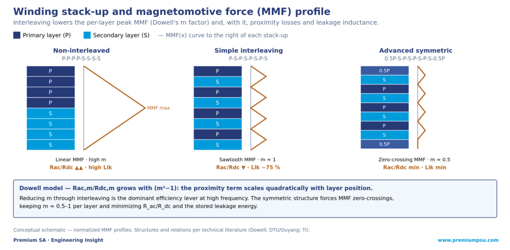
The way to tame proximity losses is to alter the spatial field distribution in the core window, abandoning simple non-interleaved stacks. Interleaving alternates primary and secondary layers with opposite current directions in adjacent layers, cancelling the net field and reducing Dowell’s m. The figure below compares three stack-ups and their MMF profile.

calculation
Figure 1 — Winding stack-up and MMF profile. Interleaving lowers the per-layer peak MMF and, with it, proximity losses and leakage.

The advanced symmetric structure 0.5P-S-P-S-P-S-P-S-0.5P —with the outer layers at half-turn and connected in parallel— forces multiple MMF zero-crossings, keeping m≈0.5–1 uniformly and minimizing both Rac/Rdc and the stored leakage energy. For fractional ratios or extreme thermal performance in the MHz range, the half-turn structure implements 180° traces in parallel on the outer layers, splitting the current and halving the peak field. And at high current, the interleaved serpentine winding snakes across several legs, maximizing window use without extra interconnection layers.

Table 3 — Winding structures and their behaviour (traced to literature).

Structure MMF profile Rac/Rdc Leakage Llk Routing / vias
Non-interleaved (P-P-P-P-S-S-S-S) Linear ramp; peak at interface Very high (accumulates m) Very high Minimal (no crossings)
Simple interleaving (P-S-P-S…) Sawtooth; moderate peaks Low (m≈1) Reduced up to −75 % High (alternating layers)
Advanced symmetric (0.5P-S…0.5P) Attenuated; cancellation at outer faces Absolute minimum (series-parallel) Very low and controlled Very high (parallel vias, symmetry)
Half-turn Shifted and symmetric to axis Very low (m≈0.5) Minimal for a given insulation Very high (fractional geometry)

Parasitics as design variables: leakage, capacitance and EMI

The planar’s tight spatial coupling maximizes mutual inductance but demands treating parasitics as active variables. Leakage inductance Llk arises from flux that closes through the window without linking both windings. In hard switching (full bridge, flyback) it is a harmful parasitic that causes overvoltages and demands snubbers; it is minimized with full interleaving and thin dielectrics. But in LLC resonant converters it is exploited: a controlled Llk is deliberately designed to act as the series resonant inductor Lr, removing a discrete component and gaining density. To tune it, magnetic shunts are inserted or the inter-layer dielectric spacing (Δh) is adjusted, which raises Llk linearly.

The high-frequency design dilemma. Reducing leakage forces primary and secondary close together, which raises the inter-winding capacitance C_inter. Under the primary’s fast dv/dt, C_inter injects common-mode displacement currents into the secondary, generating conducted EMI that demands bulky filters. It is broken with electrostatic shielding (a thin, slotted copper layer —to avoid shorting the flux— tied to a quiet ground) or with an auxiliary cancellation winding of opposite polarity (−dv/dt) that nulls the net common-mode current.

Validation: leakage measurement and hybrid analytical-FEA calibration

In a high-performance planar, Llk is under 1 % of the magnetizing inductance (often 0.1–0.2 %, in nanohenries), of the same order as the instrument leads’ own inductance. It is measured with the direct short-circuit method (a wide copper bar across the secondary + impedance analyzer at the decade of the switching frequency) or, without an HF analyzer, with the turns-ratio and AC-deviation method. In both cases it pays to build test fixtures with planar contacts and symmetrical coaxial traces to calibrate open/short at the device plane.

The one-dimensional Dowell model fails on real traces: concentric spirals concentrate the DC current at the inner radius (spirality effect), raising the real Rdc. The hybrid analytical-numerical methodology solves this without the cost of a full 3D transient: the ideal arc is computed (Rca = 2π/(σ·h_cu·ln(r₂/r₁))), the real resistance is extracted by static DC FEA with quarter symmetry, a calibration factor (Rca/R₊) is obtained and injected as a coefficient into the AC-loss formula. The result agrees with 3D transient simulations (Ansys Maxwell) within under 1 % error, in microseconds instead of hours.

Insulation and standards: clearance, creepage and IEC 60664-1

The proximity of high- and low-voltage traces demands strict compliance with dielectric standards. Clearance is the through-air distance (prevents direct arcing); creepage, the leakage path along the solid surface (prevents conductive carbonization). IPC-2221 sets minimums up to 500 V and adds a linear surcharge above that; IPC-9592, specific to power conversion, imposes more conservative criteria. High-CTI materials tolerate smaller creepages.

Distances are not read from a static table: IEC 60664-1 requires evaluating the real environment. The pollution degree (PD2 common in industry) can be reclassified to PD1 with conformal coating or potting, drastically reducing the required creepage. The overvoltage category (OVC) sets the primary clearance on mains. And altitude penalizes: above 2000 m the lower dielectric strength of air forces multiplying the clearance, with a factor of about 1.48 at 5000 m —relevant in mountain railway, high-altitude solar and avionics. Physically, creepage is multiplied by milling through slots in the FR4 between primary and secondary, forcing the leakage path to go around the cut, or by interposing insulating barriers.

Software ecosystem: open and commercial

The coupled complexity of the HF field has produced a mature software ecosystem. Premium SA prioritizes, where they meet requirements, open-source and auditable tools: they enable first-class engineering with no lock-in or licence cost, and their verifiable code fits the traceability that regulated sectors demand.

On the open side, the OpenMagnetics project stands out —a working group of the PSMA magnetics committee—: its MKF compute engine (C++) is exposed in Python via PyOpenMagnetics/PyMKF and operates on the neutral MAS format (Magnetic Agnostic Structure, a JSON schema describing requirements, construction and results, with insulation coordination per IEC 62368-1/61558). python-planar-magnetics (on PyPI) generates planar spirals respecting DRC rules, estimates Rdc correcting for spirality, and exports to KiCad (S-expressions) and DXF. For full FEA, ONELAB integrates Gmsh (meshing), GetDP (eddy-current fields coupled to SPICE) and Elmer (3D multiphysics in parallel, couplable to OpenFOAM for conjugate thermal). The Ansyas bridge (Synopsys–Würth collaboration) connects MAS to Ansys Maxwell via PyAEDT.

Table 4 — Software for planar magnetics design (verified).

Suite Licence Base / environment Capability for planars
PyOpenMagnetics / MAS Open source (MIT) Python wrapper · C++ MKF engine Proximity/skin losses, MAS JSON schema, SVG plotting
python-planar-magnetics Open source Parametric Python scripting DRC spirals, Rdc correction, KiCad/DXF export
ONELAB (GetDP/Gmsh/Elmer) Open source (GPL) General-purpose FEA + SPICE Coupled 2D/3D eddy current and conjugate thermal (OpenFOAM)
Ansys Maxwell Commercial Reference 3D EM FEA Nonlinear hysteresis, bidirectional thermal-mechanical coupling
COMSOL / CST Commercial Multiphysics FEA / FEM-FIT-TLM Coupled multiphysics; fine EMC validation
PI Expert (Planar Builder) Commercial (Power Integrations) Automated cloud synthesis Stack-up, core, widths, clearance/creepage and Gerbers

Synthesis — Premium SA engineering recommendations

  • Tuned copper thickness: keep h ≤ 2δ at the working frequency; in the MHz range, thin foils or 1–2 oz copper interleaved, never generic heavy copper.
  • Always interleave the stack: avoid continuous MMF ramps; prioritize symmetric structures (0.5P-S…0.5P) or half-turn to minimize proximity and leakage.
  • Parasitics by topology: in LLC, design Llk as the resonant inductor (removes the discrete part); in hard switching, minimize Llk and break C_inter with electrostatic shielding to a quiet ground.
  • Hybrid analytical-FEA flow: calibrate the Rac equations with a geometric factor extracted from static DC FEA; enables Pareto optimization with <1 % error versus the 3D transient.
  • Insulation by real environment: size clearance/creepage with IEC 60664-1 (PD, OVC, altitude); mill slots in the FR4 and evaluate conformal coating to reclassify PD2→PD1.
  • Open software first: OpenMagnetics/MAS and python-planar-magnetics for synthesis and losses; ONELAB/Elmer for FEA; reserve commercial suites for final multiphysics validation.

Sources and traceability

Premium SA internal catalogue: block B8 (passive/magnetic components), B7 (thermal management), B4 (resonant topologies). Companion to the Premium article «Three-phase resonant converters and planar magnetic integration» (that one, system-level integration; this one, planar-transformer design methodology).

External technical literature and tools (selection):

  • Losses and design: Dowell model; loss and leakage optimization in planars (DTU / Ouyang); Texas Instruments application notes (Topic 4, Designing Planar Magnetics).
  • Case studies: 1 kW / 1 MHz one-eighth-brick LLC (TI SSZTD94); 1 W ultra-flat isolated supply TIDA-00688 (TI TIDUB83).
  • Insulation: IPC-2221 / IPC-9592; IEC 60664-1 (insulation coordination; altitude factor ≈1.48 at 5000 m); IEC 62368-1.
  • Open software (verified): OpenMagnetics / MAS / PyMKF (PSMA Magnetics Committee WG; IEEE-PELS, 40+ models); python-planar-magnetics (PyPI, dzimmanck); ONELAB / GetDP / Gmsh / Elmer; Ansyas bridge (Synopsys–Würth).


About Premium SA

Premium SA is a Barcelona-based manufacturer of electronic power converters for railway, industrial and energy applications. With more than 900 standard product designs and over 40 years of operational experience, Premium SA supplies DC/DC converters, DC/AC inverters, AC/AC frequency converters, battery chargers, rectifiers and UPS systems from 50 W to 72 kW.

The D2x / DFR methodology integrates magnetic design —including parasitic co-design and simulation verification— from the conceptual phase, with a preference for open-source, on-premises and auditable tools, and traceable experimental validation compliant with the standards of regulated sectors.

Premium PSU
Premium SA · Barcelona, Spain · info@premiumpsu.com · +34 932 232 685 · www.premiumpsu.com
Born in Barcelona, Powering the World
ARTICLE
Data Center, Sin categoría

The 800 VDC revolution: the energy engine behind AI

PREMIUM SA · ENGINEERING INSIGHT · 800 VDC ARCHITECTURE FOR AI · 2026

The 800 VDC revolution: the energy engine behind AI

Why the data center has become an industrial energy plant, and how the sidecar, liquid cooling and observability are redrawing the power architecture.

Premium PSU


Executive summary

In the AI race, the battlefield has moved to physical hardware: data centers are ceasing to be air-conditioned halls and becoming industrial plants for high-precision energy and heat management. Energy efficiency has stopped being a sustainability goal to become the pillar of financial viability.

The technical trigger is the exhaustion of the 48-54 VDC bus. Above roughly 200 kW per rack, copper and heat impose a physical wall. The ecosystem’s answer —reached at the OCP EMEA Summit 2026 in Barcelona— is the move to 800 VDC with local conversion via «sidecar», mandatory liquid cooling and a new observability layer that turns every converter into a managed node. This article explains the why and the how, with figures corrected to authoritative sources.

Note: the source material’s figures have been adjusted to the official values (NVIDIA: −45 % copper, not 93 %; efficiency up to +5 %; water footprint per queries, not per interaction; 1 point = 1 MW/100 MW). The sources section details the traceability.

−45 %Copper with 800 VDC versus 54 VDC (NVIDIA)
≈ 16.7×Less current: ~12,500 A → ~750 A at 600 kW
100–300 kWPer-rack density that forces liquid cooling
1.2 MW800 VDC sidecar target in 2027

Why AI is thirsty for energy

Accelerated computing has changed the rules. Energy and its thermal management have become the dominant share of a modern data center’s operating cost, ahead of hardware and software. And consumption is growing: the International Energy Agency estimates data centers consume around 1.5 % of the world’s electricity today, projected to double by 2030 — the more speculative two-decade projections point to notably larger fractions.

Water is an equally real constraint: available literature places consumption at around 500 ml per 20-50 queries to a language model (not per individual interaction, as is sometimes reported), a figure that becomes decisive at campus scale. And efficiency is measured in money: improving the conversion chain by one percentage point saves on the order of 1 MW per 100 MW installed — at European electricity prices, hundreds of thousands of euros per year per installation. Efficiency is no longer a technical virtue: it is the business model.

The end of the 54 V era: the copper wall

For decades, the 48-54 VDC bus was the gold standard. But powering racks above 200 kW hits a wall of copper and heat: at 54 V, a 1 MW rack would require up to 64U of power hardware alone, with no room for compute. For the power engineer, the leap to 800 VDC is not a new invention but a rediscovery: the same high-voltage-bus and localized-conversion logic that high-speed railway traction has applied since the nineties.

Table 1 — From the 54 V bus to the 800 VDC bus (figures corrected to authoritative source).

Characteristic Traditional architecture (54 V) New architecture (800 VDC) Source
Power limit Tops out above ~200 kW Megawatt-class racks (1 MW from 2027) NVIDIA
Current (600 kW) ≈ 12,500 A ≈ 750 A (≈ 16.7× less) ST / SemiAnalysis
Copper mass (1 MW) ≈ 200 kg of busbar ≈ 45 % reduction; >150 % power through the same conductor NVIDIA (official)
Efficiency / TCO Degraded by ohmic (I²R) losses Up to +5 % end-to-end; TCO −30 % NVIDIA
Technology status Saturated (copper congestion) Scalable (electric-traction heritage) OCP Diablo 400

A note of rigour. An inflated figure circulates: that 800 VDC cuts copper by 93 % (from 200 to 13.5 kg). It is incorrect: it confuses the current ratio (≈16.7×) with the real mass reduction. NVIDIA’s official figure is a reduction close to 45 %, with over 150 % power transmitted through the same conductor. Before an engineering customer, a well-supported 45 % weighs more than a 93 % with no source.

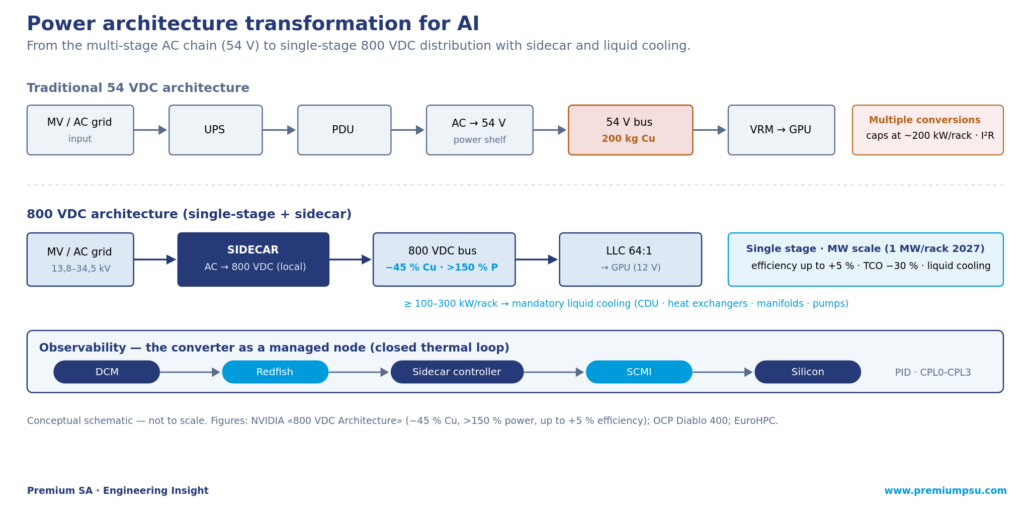
The full transformation is summarized in the schematic below: from the multi-stage AC chain to single-stage 800 VDC distribution with sidecar, liquid cooling and closed-loop observability.

800 vdc
Figure 1 — Power architecture transformation: from the multi-stage AC chain (54 V) to single-stage 800 VDC with sidecar, liquid cooling and observability. Conceptual schematic.

The sidecar: the necessary copilot for 800 VDC

The sidecar is a dedicated power rack, adjacent to the compute rack, that receives alternating current from the data center floor and converts it locally to 800 VDC. As Schneider Electric summarized at the OCP EMEA Summit 2026, «the sidecar is the immediate enabler of 800 VDC». It is not an isolated proposal: Oracle has integrated it into its reference designs and Microsoft is deploying it in its new campuses.

For the operator, it offers three strategic advantages: it enables a non-disruptive upgrade, injecting AI densities into existing AC infrastructures without redesigning the whole building’s electrical system; it isolates the fault domain, confining any electrical incident to a single rack and protecting cluster availability; and it leverages the maturity of the electric-vehicle supply chain (650-700 V semiconductors, 400 V-class capacitors and connectors), accelerating qualification and deployment.

Liquid cooling: when air is no longer enough

Concentrating massive power in small spaces has an inevitable consequence: with densities of 100 to 300 kW per rack, fan-based thermal transfer is physically insufficient. The industry is transitioning to liquid cooling, a systemic shift that moves the focus from building air conditioning to chip-level thermal management. The key components of this new era are industrial, not IT:

  • CDU (Coolant Distribution Units): the heart of the system; they pump the coolant and separate the primary from the secondary loop, enabling heat to be managed directly at the silicon instead of cooling ambient air.
  • Heat exchangers: transfer the thermal energy outward with high efficiency; they are the critical interface for reusing waste heat in industrial networks.
  • Manifolds and secondary loops: precision piping that distributes the flow; they require specific materials and control valves to avoid leaks and pressure drops at high density.
  • Precision pumps and dielectric fluids: maintain constant flows of glycol water or dielectric oils, guaranteeing long-term reliability with no corrosion or electrical conductivity.

The converter as a managed node: Redfish and SCMI

This physical infrastructure needs a brain to coordinate energy and heat in real time, and it elevates the role of the power converter: it ceases to be a passive component to become an intelligent node that speaks two languages — Redfish, the data center management standard, and SCMI, the communication with the silicon. The telemetry and control flow runs the hierarchy DCM → Redfish → sidecar controller → SCMI → silicon, closing a thermal loop: the system reads the chip temperature and, via a PID controller, adjusts power and flow before throttling occurs.

The critical observability tasks are three: expose the CPL0 to CPL3 capping levels (from sustained operation to the critical limit); execute power-capping (POWERCAP) commands in milliseconds so as not to overload the grid; and provide semiconductor and transformer temperature telemetry with tens-of-milliseconds granularity, feeding the thermal PID. Hardware that does not expose this telemetry precisely is left out of the 30-year service contracts.

2027-2030 roadmap

Table 2 — Transition timeline (aligned with the Premium AI Data Center WhitePaper).

Phase Technology milestone Reference power Architecture
2027 Massive deployment of 800 VDC sidecars 1.2 MW / rack High-density hybrid infrastructures
2028-2029 Room-scale centralized DC distribution 5 MW Massive SCMI / Redfish adoption
2030 Solid-state transformers (SST) 10 MW No magnetic transformer; PUE ~1.10

Conclusion: Barcelona at the epicentre

This paradigm shift is a unique industrial opportunity. Barcelona —home to the Barcelona Supercomputing Center, designated a node of the EuroHPC AI Factories with an investment close to €198 million— and Microsoft’s multi-campus expansion in Aragón (with PUE 1.12 and zero water) place the region at the epicentre of European sovereign digital infrastructure. This is not a mere technology upgrade, but an ecosystem where high-fidelity power electronics and industrial thermal management are the new sovereigns. In the AI era, efficiency is not an option: it is the business model.

Sources and traceability

Premium SA internal coherence: AI Data Center WhitePaper Premium PSU (Unified) and v2.0; WhitePaper «Railway discipline for AI»; OCP EMEA Barcelona 2026 article; CEO op-ed «Barcelona, the epicentre of the AI energy revolution» (30/04/2026); strategic outlook «Spanish industry in the AI-factory supply chain».

Verified external sources (corrected figures):

  • 800 VDC: NVIDIA Technical Blog and «800 VDC Architecture» page (−45 % copper, >150 % power per conductor, up to +5 % efficiency, TCO −30 %, maintenance −70 %, 200 kg/rack at 54 V, 1 MW/rack from 2027); ST Blog and SemiAnalysis (≈12,500 A → ≈750 A); OCP Diablo 400; Schneider Electric quote (OCP EMEA 2026).
  • Sustainability: IEA (≈1.5 % of world electricity today, projected to double by 2030); literature on AI water footprint (≈500 ml per 20-50 queries).
  • Spanish hub: EuroHPC JU / BSC-CNS (BSC AI Factory, ≈€198 M, MareNostrum 5 upgrade in 2026); Microsoft communication on Aragón (PUE 1.12, zero water).

Editorial note: corrected from the source draft are the copper reduction (93 % → ≈45 %), the water footprint (per interaction → per 20-50 queries), the 1 point = 2 MW → 1 MW per 100 MW relation, and the 85 % OpEx and 7-8 % electricity figures qualified as projections. No published figure contradicts the Premium corpus or the authoritative sources.


About Premium SA

Premium SA is a Barcelona-based manufacturer of electronic power converters for railway, industrial and energy applications. With more than 900 standard product designs and over 40 years of operational experience, Premium SA supplies DC/DC converters, DC/AC inverters, AC/AC frequency converters, battery chargers, rectifiers and UPS systems from 50 W to 72 kW.

As a Barcelona-born industrial company and OCP member, Premium SA brings to the AI ecosystem the 40-year RAMS discipline forged in the most demanding environments —railway traction, substations, defence and energy.

Premium PSU
Premium SA · Barcelona, Spain · info@premiumpsu.com · +34 932 232 685 · www.premiumpsu.com
Born in Barcelona, Powering the World
Innotrans
Events and corporate news, Sin categoría

Railway Power Solutions at InnoTrans 2026 | Premium PSU

InnoTrans 2026 · Technical Article

ENGINEERED FOR ROLLING STOCK — PREMIUM PSU’S RAILWAY POWER PORTFOLIO AT INNOTRANS 2026

This is a technical tour of the converters, inverters, drives and chargers on the stand — and the rolling-stock applications they are built for.

Premium PSU
·
Berlin · 22–25 September 2026 · Hall 17, Stand 425
900+
Custom designs since 1981
50 W–72 kW
Full conversion range
14 weeks
Custom prototype lead time
100%
Final test on every unit


Founded in Barcelona in 1981, Premium PSU brings more than four decades of power-conversion experience and over 900 custom designs to InnoTrans 2026.

One Supplier, the Full Conversion Matrix

Premium PSU designs and manufactures the complete conversion matrix used on board a modern train — AC/DC power supplies, DC/DC converters, DC/AC inverters, AC/AC variable frequency drives and UPS — from 50 W to 72 kW. Every railway product is engineered to EN 50155, with fire-and-smoke behaviour to EN 45545-2, shock and vibration to EN 61373 and the EMC performance the onboard environment demands. Sourcing the whole matrix from one qualified supplier removes multi-vendor qualification overhead and the grey areas of responsibility that appear when converters from different makers share the same bus.

Spotlight — VDX-6K

The product Premium PSU is putting front and centre at InnoTrans 2026 is the VDX-6K: a railway-grade AC/AC three-phase frequency converter developed for multi speed HVAC condenser-fan control on high-speed trains and small compressors. It acts as a controlled interface between a train-side 400 VAC three-phase supply and the HVAC rotating loads, livering a selectable sinusoidal output from 320 to 480 VAC and 40 to 60 Hz, where a standard industrial drive would not fit either mechanically or electrically.

Fan operation is managed through simple discrete hardware inputs, selecting the required V/F operating point — reduced, nominal or high speed — while relay outputs report input, output and temperature status back to the HVAC controller. An RS-232 interface remains available for parameter setting, monitoring and maintenance. Because normal operation can be handled through hardware signals rather than continuous network communication, the VDX-6K reduces system integration complexity and limits unnecessary communication exposure.

Engineered for railway rolling stock applications according to EN 61287-1 and EN 50155, the VDX-6K combines 6.4 kW nominal power, 11.6 kW peak power, IP54 protection, EN 61373 shock and vibration compliance, and EN 45545-2 fire and smoke compliance in a compact closed-case format.

Catenary-Fed Power — The Spark Series

The Spark Series takes power straight from the catenary. The OVX-6400 is a 6.4 kVA three-phase pure sine wave DC/AC inverter that supplies a stable 400 VAC auxiliary line directly from a 600/750 VDC catenary, while the CVS-280 is a compact DC/DC converter used as a low-battery-voltage starter. Both remove intermediate conversion stages, saving space and losses on vehicles where the catenary is the only primary source.

Isolated DC/DC — The CRS and CLS Families

Premium PSU offers two complementary railway DC/DC converter platforms for different system architectures.

The CRS family is designed for higher-power chassis-mount applications where the input and output voltages are selected according to the train architecture. CRS can therefore support application-specific DC/DC voltage combinations, such as converting from one battery voltage to another auxiliary DC bus, while offering higher power levels, robust mechanical integration, redundancy or parallel operation, hold-up capability, active reverse-polarity protection and different cooling options depending on the model.

The CLS family covers railway battery applications from 40 W to 500 W with regulated 24 VDC output as standard, plus 12, 15 and 110 V variants. Models up to 300 W use an ultra-wide 11:1 input range (16.8–137.5 V), covering all nominal battery voltages — 24, 36, 48, 72 and 110 V DC — in a single reference. The CLS-500 targets 72/110 V systems with a 4:1 extra-wide range (50.4–137.5 V). Across the family, this reduces the number of variants needed for qualification, stock and spares management in mixed fleets..

In short, CRS is the higher-power platform for application-specific input/output voltage combinations; CLS is the wide-input platform for regulated 24 VDC or 110 VDC auxiliary outputs.

Auxiliary AC — TDS-3300 and the SiC HVAC Roadmap

The TDS/TDX AC Master series is an isolated AC/AC voltage and frequency changer that can also operate from a high-voltage DC input as a DC/AC inverter. The TDS version provides a regulated 230 VAC single-phase output, while the TDX version provides a regulated 400 VAC three-phase output, both with sinusoidal waveform and adjustable frequency capability. This makes the platform suitable for railway auxiliary AC supply and hotel-load applications

Energy and Hybrid Traction — BDS-10K

For battery-electric and hybrid platforms, the BDS-10K is a scalable battery charger that can be paralleled — up to four units for 40 kW — and is qualified to EN 50155. It supports the charging and energy-management needs of BEMU and hybrid diesel-electric trains, where reliable DC energy is as critical as traction itself.

Designed, Built and Tested in Barcelona — by a Team of Experts

What ties the portfolio together is process. Premium PSU’s engineering, test laboratory and production are co-located in Barcelona, so the loop between specification, qualification and manufacturing never crosses time zones or supply chains. A dedicated team of power-electronics experts works from a quantified mission profile through a Design-for-Reliability flow, delivering custom prototypes in as little as 14 weeks — about half the typical industry cycle — and backing every unit with 100% final test. With more than 900 custom designs since 1981, the team’s know-how keeps NRE costs and schedules low while meeting the most demanding rolling-stock requirements.

Meet Our Experts at InnoTrans 2026

Railway Power Solutions at InnoTrans 2026 | Premium PSU

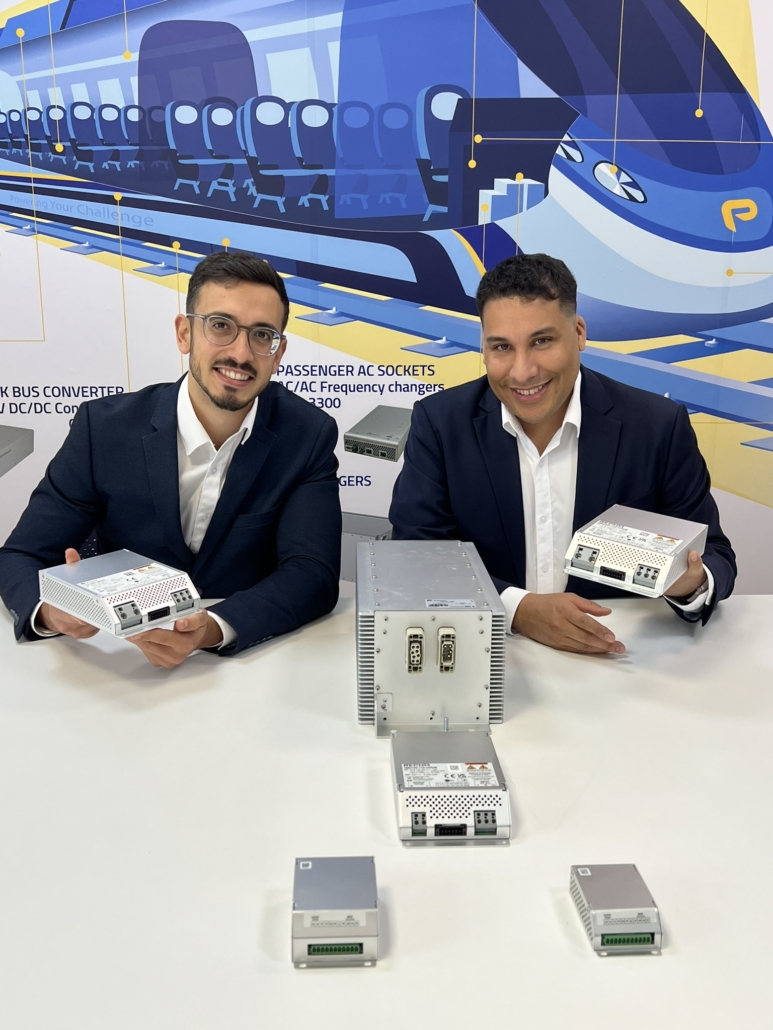
Premium PSU’s DACH Export Area Manager and Product Manager presenting the VDX-6K IP54 and CLS railway DC/DC series ahead of InnoTrans 2026.

Premium PSU will present this full portfolio at InnoTrans 2026 — Berlin, 22–25 September, Hall 17, Stand 425. Our engineering team will be on the stand to discuss specific operating profiles, qualification requirements and custom developments. The most useful conversation does not start with a datasheet — it starts with your application, your operating profile and your timeline. Book a meeting with our experts in advance. Contact us!


About Premium PSU

Founded in Barcelona in 1981, Premium PSU has more than four decades of power-conversion experience and over 900 custom designs. Engineering, test laboratory and production are co-located in Barcelona, covering the full railway conversion matrix from 50 W to 72 kW.

Born in Barcelona, Powering the World — www.premiumpsu.com

Premium PSU · Born in Barcelona, Powering the World
www.premiumpsu.com
Multilevel Inverters: NPC, FC, CHB and the Road to RDC-ML
Application Notes, Railway & Transportation, Sin categoría

Multilevel Inverters: NPC, FC, CHB and the Road to RDC-ML

Engineering Insight · Power Conversion Architecture

Multilevel Inverters: NPC, FC, CHB and the Road to RDC-MLI

From conventional two-level to neutral-point clamped, flying capacitor, cascaded H-bridge and reduced device count topologies — architectural synthesis for traction, grids and renewables

Premium PSU
|
Premium SA · Barcelona
|
April 2026
|
#PowerElectronics #MultilevelInverters #PremiumPSU
1981Year NPC Was Invented
<5%THD in 7+ Level CHB
1/2Per-switch Voltage Reduction
MWPower Range Where MLI Is Mandatory


Executive Summary

Multilevel inverters (MLI) represent the architectural evolution that made medium-voltage and high-power power electronics viable. Their fundamental principle — synthesising a stepped voltage waveform from several lower-voltage DC sources — solves simultaneously four problems that the conventional two-level inverter could not address: the blocking-voltage limit of commercial semiconductors, the harmonic distortion that penalises power quality, the dv/dt stress that destroys motor insulation, and the switching losses that prevent reaching efficiencies above 97% in the megawatt range.

The four structural advantages of MLI. (1) Divided blocking voltage — each semiconductor blocks only V/(m−1). (2) Reduced THD without sacrificing power — stepped waveform drops below 5% THD with no filter, complying with IEEE 519 directly. (3) Lower dv/dt — transitions occur between adjacent levels, reducing motor insulation stress by orders of magnitude. (4) High efficiency — semiconductors switch at low frequencies; overall efficiency approaches 98% in megawatt applications.

The Fundamental Principle — Additive Voltage Synthesis

A conventional two-level inverter has two possible output states per phase: +V/2 and −V/2. The transition between them is abrupt and requires a high switching frequency and a bulky output filter to approximate a sinusoid. Each switch must block the full DC-bus voltage, imposing a hard limit: above roughly 1700 V of bus, commercial IGBTs start running short on margin; above 3.3 kV, they simply do not exist as a single part.

The multilevel inverter solves this with an additive synthesis strategy: the output voltage is constructed by summing smaller contributions from intermediate DC-bus levels or independent sources. The resulting staircase waveform naturally approximates a sinusoid without high-frequency switching. The structural cost: more components than a two-level inverter — more switches, isolated gate drivers, clamping elements. Topology selection is the consequence of systematically analysing when that cost is justified.

The Three Classical Topologies

NPC — Neutral Point Clamped

Introduced by Nabae, Takahashi and Akagi in 1981, the NPC divides the DC bus into (m−1) levels through series capacitors and uses clamping diodes to connect intermediate nodes to switching points. The DC bus is single and shared by all three phases, minimising total capacitance. The main limitation is voltage imbalance in the intermediate DC-bus capacitors — manageable at m=3, but for m≥5 the control complexity becomes prohibitive. Practically all commercial NPC products are limited to three levels.

Aspect Characteristic (m-level NPC) Design Implication
Active switches 2(m−1) per phase Linear growth with m
Clamping diodes (m−1)(m−2) per phase Quadratic — limits practical m to 3
DC sources 1 (single bus) Architectural advantage over CHB
Dominant application Three levels (m=3) STATCOM/SVC, drives 690 V–4.16 kV, grid-tied PV

FC — Flying Capacitor

Proposed by Meynard and Foch in 1992, the FC replaces clamping diodes with floating capacitors holding intermediate voltages. Every switch blocks the same voltage, and redundancy of switching states allows active capacitor balancing through appropriate state selection each switching period — more manageable than the NPC. The disadvantage is quadratic capacitor growth (a 5-level FC requires 6 floating capacitors per phase) and a complex pre-charge startup routine. The FC dominates high-speed railway traction where per-cell modularity justifies the cost.

CHB — Cascaded H-Bridge

The CHB series-connects multiple complete single-phase H-bridges, each fed by an independent isolated DC source. The output voltage is the algebraic sum of each cell’s contribution. A CHB with N cells per phase produces 2N+1 levels. Its three structural advantages — pure modularity, absence of inter-capacitor balance issues, fault tolerance through cell bypass — make it the preferred topology when the application provides separate DC sources naturally (batteries, PV strings, multi-pulse transformers). Without that condition, NPC or FC are preferable.

Topology Key Components Main Advantage Main Disadvantage
NPC 2(m−1) IGBTs + (m−1)(m−2) diodes Single shared DC bus Capacitor imbalance limits to m=3
FC 2(m−1) IGBTs + (m−1)(m−2)/2 cap. Natural balance via redundant states Quadratic capacitors; complex pre-charge
CHB 2(m−1) IGBTs + (m−1)/2 isolated sources Pure modularity, fault tolerance Needs isolated DC sources or multi-pulse transformer

Modulation Strategies

Multi-carrier SPWM and Phase-Shifted PWM (PS-PWM)

The natural extension of classical SPWM uses (m−1) triangular carriers per the Phase Disposition (PD), Phase Opposition Disposition (POD), or Alternative POD variants. PD minimises line-voltage THD and is preferred for NPC; POD minimises current THD. PS-PWM is specific to the CHB: each H-cell uses its own carrier, shifted 360°/N relative to the next, effectively multiplying the apparent output switching frequency by N without any individual switch switching faster — enabling very high efficiency at megawatt scale.

Selective Harmonic Elimination (SHE-PWM)

For very-high-power applications where switching losses dominate, SHE-PWM precomputes offline the switching angles that cancel specific harmonics (5th, 7th, 11th, 13th). For N pulses per quarter cycle, exactly N−1 harmonics can be eliminated. Switching losses drop to approximately 1% versus 3–4% for conventional PWM. The limitation is slow transient response and numerical instability beyond 5 levels.

Space Vector Modulation (SVM)

SVM operates on the αβ space of three-phase output voltages. Each switch-state combination corresponds to a vector, and the reference is synthesised as a linear combination of adjacent vectors. For a 3-level inverter: 27 vectors. For 5 levels: 125. For 7 levels: 343. Algorithmic complexity scales with m but SVM offers optimisable THD and high dynamic performance, making it the preferred strategy for FACTS and high-performance drives.

The Current Frontier — RDC-MLI and Asymmetric Topologies

Classical topologies share a scaling problem: switches grow with levels (a 7-level MLI requires 12 switches per phase; a 21-level one, 40). For 30-year reliability commitments, this escalation becomes unacceptable. Two research directions address it:

RDC-MLI (Reduced Device Count) architectures split the inverter into a level-generation stage (high frequency, determines magnitude) and a polarity-generation stage (fundamental frequency, decides sign). This separation reduces switching losses significantly. RDC-MLIs achieve 7 levels with 8–10 switches versus 12 for classical NPC/FC.

The asymmetric exponential trick. If CHB cells produce voltages in binary geometric progression (Vdc, 2·Vdc, 4·Vdc, 8·Vdc), a 4-cell inverter produces 31 levels instead of the symmetric 9 — with the same switch count. Ternary asymmetry (powers of 3) maximises level density (3N theoretical levels) at the cost of control complexity. The trade-off: cells are no longer interchangeable, losing the classical CHB’s pure modularity.

Applications — Where MLI Is the Mandatory Solution

Railway Traction

High-speed traction (Talgo, Stadler, ICE) uses DC buses of 3 kV or 1.5 kV fed from the catenary, driving megawatt-scale motors. The three-level NPC has dominated this segment since the 1990s. The transition to SiC in some recent designs reopens the two-level debate — SiC allows faster switching without loss penalty — but the topology decision remains application-specific.

FACTS — STATCOM and SVC

A modern 100 MVAr substation STATCOM can have hundreds of H-cells per phase, each switching at a few hundred Hz, summing output voltages up to 33 kV without a step-up transformer. CHB modularity fits perfectly with qualified replicated H-cell manufacturing, and bypass fault tolerance keeps operation running with degraded performance — exactly what transmission operators require.

HVDC and Transmission

Modern VSC-HVDC uses the MMC (Modular Multilevel Converter) — an advanced CHB variant with hundreds of submodules per arm. European inter-country submarine interconnections (NorNed, Cobra Cable, Viking Link) use MMC with several hundred levels, achieving THD below 1% directly at the connection point. Cell redundancy makes per-cell failure irrelevant: with 400 cells per arm, the system tolerates dozens of failures without service loss.

Large-Scale Renewables and EV

PV plants use CHB naturally (each H-cell fed by a panel string); wind farms use three-level NPC for back-to-back converters; offshore wind increasingly uses MMC via HVDC. In automotive, the transition to 800 V battery buses in premium EVs (Porsche Taycan, Audi e-tron GT, Hyundai Ioniq 5/6) makes three-level inverters with 600–650 V SiC devices an increasingly attractive alternative to single-level designs with tight voltage margin.

Diagnosis and Troubleshooting

Observed Symptom Probable Cause Corrective Action
NPC capacitor imbalance Deficient neutral-point control Implement active control via redundant state selection
High THD at low modulation Modulation index M < 0.5 in SPWM Switch to SHE-PWM or third-harmonic injection
FC capacitor overvoltage Active balance algorithm failure Review redundant state selection; verify pre-charge
CHB cell current imbalance Different battery SOC or DC sources Adaptive asymmetric modulation to redistribute power
Elevated common-mode spikes Modulation breaks 3-phase symmetry Select PD-SPWM if NPC; review switching sequence
Saturated transient response (SHE) Precomputed table out of regime Hybrid SHE + SPWM in transients; revert to SHE in steady state

Topology Selection Matrix

Design Question Favours NPC Favours CHB
Single shared DC bus? Yes — native to NPC No — CHB needs isolated sources
Application provides separate DC sources? No Yes — batteries, panels, multi-pulse transformer
Levels required? Up to 3 5 or more
Fault tolerance via cell bypass critical? No Yes
LRU maintenance modularity important? Less Yes — identical replaceable cells
The closing argument. Multilevel inverters are not an emerging technology — they have been the consolidated solution for medium-voltage, high-power power electronics for three decades. What continues evolving are the variants: three-level NPC consolidated, MMC dominating HVDC, RDC-MLI and asymmetrics as an active research frontier, SiC reopening the topology debate in the medium-power range. Topology selection is not a matter of taste: it is the consequence of a systematic analysis of bus voltage, waveform quality, DC source availability, modularity criticality, and maintainability horizon. Premium SA applies this analysis at the D2W gate of every new programme — because the right topology, well-chosen modulation, and rigorous thermal control are what differentiates a megawatt converter that meets 30 years of service from one that fails at five.


About Premium PSU

Premium SA is a Barcelona-based specialist in custom power electronic converters for railway, industrial, defence, and energy applications. Over 900 standard designs, 40+ years of operational experience, supplying converters from 50 W to 72 kW.

www.premiumpsu.com · info@premiumpsu.com · +34 932 232 685 · Born in Barcelona, Powering the World

Premium PSU
© 2026 Premium SA · www.premiumpsu.com
Engineering Insight · Power Conversion Architecture · April 2026

Premium SA — Born in Barcelona, Powering the World

Need a custom power supply for your critical application?

Our engineering team designs custom power electronics solutions for railway, defence, energy and industrial applications.

Contact our engineering team
View product catalogue
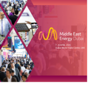
Premium PSU at the exhibition Middle East Energy 2025
Events and corporate news, Sin categoría

Premium PSU at the exhibition Middle East Energy 2025

See you at the 48th edition of Middle East Energy!

Date: April 7 – 9, 2025
Location: Dubai World Trade Centre, UAE
Premium PSU Pavilion: H2. E31

For over 46 years, Middle East Energy has been a leader in the energy transition, exploring advancements in products and solutions that contribute to the creation of more efficient and effective electrical systems. This event has become one of the most reputable and longest-standing in the energy industry.

The energy sector is in constant evolution, meaning energy systems must not only adapt to new regulations and changing consumer preferences but also incorporate technological advancements. Middle East Energy offers the opportunity to connect with international energy suppliers, discover innovative solutions that are transforming the energy landscape, and build new business relationships.

Premium PSU will be showcasing two new solutions designed for the energy industry. We will present the new FlexStorm series, which includes high-frequency rectifiers, standing out for their flexibility, reliability, and power density in industrial environments. This compact and robust system is 100% scalable and is offered as a modular solution, ranging from the power module to the subrack, including control, visualization, and of course, the complete solution as a cabinet.

Additionally, we will continue to showcase our standard solutions, such as DC/AC inverters, DC/DC converters, and battery chargers.

The first step towards energy transition.

The 48th edition of Middle East Energy will bring together 800 exhibitors, 3 powerful conferences, 5 product sectors, and an exclusive VIP program—all in one place! Join over 20,000 energy professionals from April 7-9, 2025 at the Dubai World Trade Centre, UAE.


Get your free visitor’s pass
Powering Energy Technology in Monterrey México with Premium PSU
Sin categoría

Powering Energy Technology in Monterrey México with Premium PSU

Powering Energy Technology in Monterrey with Premium PSU

Premium PSU is proud to announce its participation in Expoeléctrica Monterrey, México, one of the most prominent events in the electrical and energy sector across Latin America. This year, the exhibition will take place from November 5th to 7th at the Cintermex Exhibition Center, and we are excited to invite you to our booth 710, where we will showcase our latest cutting-edge power supply solutions.


What to Expect from Premium PSU at Expoeléctrica 2024?

At this year’s Expoeléctrica Monterrey, Premium PSU will be presenting an innovative range of products, designed to meet the most demanding needs across various industrial and commercial sectors. Here is a preview of some of the advanced solutions you will be able to see firsthand:

  • ODX-6000: 6000W Three-phase DC/AC Inverters for Industrial and Railway Applications
  • CKR-2000: Redundant DC/DC Converters up to 1960W
  • CRS-240: 180-280W Industrial DC/DC Converters
  • ODS-3000: 3000VA DC/AC Inverters for Industrial and Railway Applications
  • ACB-3000: Static Transfer Switch
  • EDS-500: 500W DC UPS for Guaranteed Power during Unexpected Outages
  • EPS-120: 120W (180W peak) DC UPS Systems, 48V with Ethernet
  • ECS-200: 200W DC UPS Systems


New! As a new feature, we will be unveiling the latest version of the ThyriStorm, a rectifier cabinet designed for high-voltage (AT/MT) substations.


Why You Should Visit Us

Don’t miss out on the opportunity to discover the latest trends and innovations in power supply technology, proudly 100% manufactured in Europe. Our team will be ready to provide live demonstrations, answer your questions, and discuss how our solutions can help you meet your operational needs.


See You There!

We look forward to welcoming you at booth 710 at Expoeléctrica Monterrey 2024. Be sure to visit us to learn more about how Premium PSU is powering energy technology in Monterrey.

4.5 & 6.5kW Thyristor Technology

Premium PSU’s ThyriStorm is our latest rectifiers family, an uninterruptible power supply based on a thristor technology, the most reliable and lasting technology due to the robustness of its power elements. These semiconductor devices are aimed to control electric power and current by acting as a switch, bringing a sturdy and free-of-maintenance solution for a wide range of inddustrial environments.

Categories

  • Application Notes
  • Behind Premium PSU
  • Case Studies by industry
  • Case Studies by product
  • Custom solutions
  • Data Center
  • DC/AC inverters
  • DC/DC converters
  • Defense
  • Energy
  • Events and corporate news
  • High Tech
  • Railway & Transportation
  • Sin categoría
  • UPS
  • Whitepapers

Categoria

Premium

At Premium PSU, we are specialists in designing and manufacturing power conversion systems for the industrial market. Our product range includes high reliability power supplies from 50W to 72kW.

PREMIUM PSU
C/ Dolors Aleu, 19-21, 2nd Floor
08908 – Hospitalet de Llobregat
Barcelona-SPAIN
t.+34 93 223 26 85

Born in Barcelona Powering the World

© Copyright 2026 - Premium PSU | Power supplies equipment and systems
  • Legal Note
  • Cookie Policy
  • Complaints
  • Sales General Terms
Scroll to top Scroll to top Scroll to top
Manage Cookie Consent
We use technologies like cookies to store and/or access device information. We do this to improve browsing experience and to show (non-) personalized ads. Consenting to these technologies will allow us to process data such as browsing behavior or unique IDs on this site. Not consenting or withdrawing consent, may adversely affect certain features and functions.
Functional Always active
The technical storage or access is strictly necessary for the legitimate purpose of enabling the use of a specific service explicitly requested by the subscriber or user, or for the sole purpose of carrying out the transmission of a communication over an electronic communications network.
Preferences
The technical storage or access is necessary for the legitimate purpose of storing preferences that are not requested by the subscriber or user.
Statistics
The technical storage or access that is used exclusively for statistical purposes. The technical storage or access that is used exclusively for anonymous statistical purposes. Without a subpoena, voluntary compliance on the part of your Internet Service Provider, or additional records from a third party, information stored or retrieved for this purpose alone cannot usually be used to identify you.
Marketing
The technical storage or access is required to create user profiles to send advertising, or to track the user on a website or across several websites for similar marketing purposes.
  • Manage options
  • Manage services
  • Manage {vendor_count} vendors
  • Read more about these purposes
Preferences
  • {title}
  • {title}
  • {title}