
Tag Archive for: power electronics
 Application Notes
Open innovation and strategic partnerships: more value for our customers
In an increasingly demanding and competitive world, having a reliable supplier is no longer enough. You need a partner who evolves with you, anticipates market needs, and offers flexible, efficient, and customized solutions. At Premium PSU, we believe the key to delivering this kind of added value lies in strategic partnerships and open innovation.
Read more
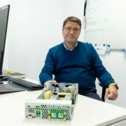 Behind Premium PSU
The innovation process at Premium PSU: turning customer challenges into real power electronics solutions
At Premium PSU, innovation is never a matter of chance—it’s a repeatable, structured process built on deep customer insight, technical expertise, and strategic collaboration. Under the leadership of CTO Xavier Cabré, we have positioned innovation in power electronics as the engine driving high-value, high-reliability solutions for critical sectors: railway, energy, industrial automation, and data centers.
Read more
 Application Notes, Data Center
From the 800 V Railway Bus to the AI Rack: The Power Conversion Chain Premium Already Knows
From the 800 V Railway Bus to the AI Rack: The Power Conversion Chain Premium Already Knows
How experience with 800 V traction converters applies to the 800 VDC sidecar architecture for AI data centres: GaN, the ALL2GaN programme and the EV supply chain.
Contents
The European ALL2GaN programme closed its thirty-six months of work in April 2026, at the same time as the AI data centre ecosystem was holding its largest annual gathering in Barcelona. The timing is telling: it marks the moment at which European gallium nitride and the high-voltage DC conversion architecture of the data centre converge on the same point of the industrial roadmap. This article reviews the data points presented at the OCP EMEA Summit 2026 that support this convergence with verifiable external evidence.
The convergence the summit confirmed
The convergence between the 800 V bus of railway traction and the 800 V bus of the AI data centre had until recently been a prospective thesis. The OCP EMEA Summit 2026 turned it into an established fact, documented by three independent industrial sources.
Schneider Electric set the limit of the 54 VDC bus at 400 kW/rack — the same threshold above which HVDC architecture becomes necessary, not optional. OmniOn Power quantified the difference: moving from the ORv3 chain (480 V → 54 V → 12 V → core, η 83.8 %) to the Next Gen 800 V chain (480 V → 800 V → 54 V → 12 V → core, η 85.8 %) saves 1.9 percentage points of efficiency — 2 MW for every 100 MW of installed DC capacity. Eaton displayed at the CCIB Innovation Village a physical prototype of the 800 V DC Side Car with a 33 kW ORV3 Power Shelf and scalable DC connectors at 63, 125 and 250 A.
The most significant data point, however, was not a number but a sentence. Schneider Electric, in its Day 2 plenary keynote, justified the 800 V sidecar with four arguments, the last of which was: leverages established EV supply chain. The EV supply chain — the same value chain in which Premium operates with its portfolio of converters for traction, e-mobility and railway auxiliaries — is the argument one of the world’s leading energy management manufacturers used to explain why the 800 V sidecar is the lowest-risk option in the short term.
“48–54 VDC rack power distribution and 480 VAC supply voltage approaches reach practical limits beyond ~400 kW/rack.”
— Schneider Electric, OCP EMEA Summit 2026, Barcelona, 30 April 2026
For a broader overview of the architecture, see The 800 VDC revolution: the energy engine behind AI.
ALL2GaN T6.2 Transport: programme context
The ALL2GaN programme — Affordable smart GaN IC solutions for greener applications — was launched in May 2023 in Villach and closed in April 2026. Coordinated by Infineon Technologies Austria AG, funded by the Chips Joint Undertaking (successor to KDT-JU) and framed within the European Chips Act and the Green Deal, it involved 45 industrial and research partners from twelve European countries.
Premium SA participates in the programme’s Transport cluster as a contributor to the development of compact power electronics building blocks for auxiliary applications. The UC3 use case from the official WP6 M36 deliverable defines the technical context: power converters for traction auxiliaries meeting the temperature, vibration, EMC and reliability requirements of the railway environment certified to EN 50155. This is exactly the design discipline profile the 800 V sidecar for data centres requires.
Why GaN is the sidecar technology
Gallium nitride is not merely an incremental improvement over silicon for DC/DC converters. It is the technology that makes possible the WBG DC/DC shelf stage of the Next Gen 800 V chain — the conversion from 800 V to 54 V at η 98.50 % in a high power density format.
GaN’s advantages over silicon in this context are threefold. First, the switching frequency can be five to ten times higher than conventional silicon, reducing the size of magnetic components and enabling power densities above 40–60 W/in³ on platforms with PCB-integrated planar magnetics. Second, switching losses are dramatically lower, with peak efficiencies above 97–98 % in real operation — not just catalogue conditions. Third, compared to SiC, GaN offers a complementary sweet spot in the medium-voltage, high-frequency band that is exactly the one dominating the WBG DC/DC shelf stage of the 800 V sidecar.
The contribution of the ALL2GaN programme is that these advantages now have a verified industrial value chain in Europe: from substrate to packaging, from reliability to application, production can be carried out entirely within the Union. This answers the industrial sovereignty question the sidecar architecture will face as regulated European hyperscalers demand supply chain traceability for their power components.
The EV supply chain as a bridge between worlds
The Schneider Electric phrase — leverages established EV supply chain — has an immediate practical implication for any power electronics manufacturer with a background in traction or e-mobility.
The components that make the 800 V sidecar possible — high-current DC connectors, high-voltage DC busbars, 4,000–5,000 A DC circuit breakers, copper cables with insulation for 800–1,000 V — are the same components the EV industry has standardised over the past decade. The technical qualifications, insulation tests, DC arc tests and earthing protocols developed for the electric vehicle are directly applicable to the data centre sidecar.
For Premium SA, which has operated for over 40 years in the railway and industrial power electronics supply chain for high-reliability applications, this has a direct technical reading: the company’s industrial track record is not just a credibility antecedent — it is the technical foundation that the sidecar market requires.
Key data points presented at OCP EMEA Summit 2026
| Data point | Technical implication |
|---|---|
| 54 V bus limit: ~400 kW/rack (Schneider Electric) | Defines the threshold above which HVDC distribution becomes necessary. A publicly verifiable data point. |
| Copper mass 200 kg → 13.5 kg per 1 MW rack (OmniOn Power) | Quantifies the physical and material advantage of 800 V distribution. |
| Chain efficiency gain: +1.9 pp (ORv3 83.8 % → 800 V 85.8 %) (OmniOn Power) | Concrete efficiency improvement across the full conversion chain, with public attribution. |
| “Leverages established EV supply chain” (Schneider Electric) | Components, qualifications and test practices from traction and e-mobility carry over to the 800 V sidecar. |
| Physical 800 V DC Side Car prototype (Eaton) | Confirms the architecture has moved from literature to product engineering. |
Key takeaway: the convergence of the 800 V bus of railway traction with the 800 V bus of the AI data centre is no longer a thesis but an industry consensus, as the OCP EMEA Summit 2026 confirmed. Schneider Electric set out the case for the sidecar. Eaton showed a physical prototype. OmniOn Power quantified that every 100 MW of DC capacity installed at 800 V instead of 54 V saves 2 MW in losses — and that the copper mass per 1 MW rack drops from 200 to 13.5 kg.
Sources
- ALL2GaN (Chips JU, formerly KDT-JU) — WP6 M36 public deliverable (UC3, T6.2 Transport).
- Schneider Electric — keynote, OCP EMEA Summit 2026 (30 April 2026): “Next-generation AI rack densities”, “The sidecar is the immediate enabler.”
- OmniOn Power — Philip Zuk keynote, OCP EMEA Summit 2026 (29 April 2026): ORv3 vs. 800 V chain and Osprey portfolio.
- OCP Foundation — DCF Power Distribution LVDC v1.0 (29 April 2026).
Power designed for your application
Premium SA designs and manufactures industrial power converters in Barcelona for railway, data centre and electrification applications.
 Application Notes
The First Prototype Admits No Second Chance
The First Prototype Admits No Second Chance
Why we simulate before soldering: the integrated simulation, quantitative reliability and accelerated test chain behind custom power electronics delivered on time.

Born in Barcelona, Powering the World
In power electronics for critical sectors — railway, defence, energy, digital infrastructure — the custom project does not allow the iterative cycle of the catalogue product. Production runs are short. Deadlines are contractually binding. The first prototype delivered to the customer is validated against the entire contract, not against a simplified preliminary version.
The consequence is structural: success at the first prototype is not a desirable goal, it is the condition that makes the business model work. When a railway customer needs a converter operating at −40 °C, or an AI application requires dissipating more than 700 W/cm² locally, the design cannot be closed “by eye”. Whether a project delivers at the first prototype or iterates three times is decided before the first PCB is manufactured.
The constraint that defines the sector
Typical production runs in custom railway or defence projects sit between 50 and 500 units. The product learning curve runs out before the cost of a partial redesign is covered, so the catalogue business model — amortising iteration over thousands of subsequent units — does not apply. Every deviation detected when validating the first prototype has three possible outcomes, all costly: redesign with replanning, acceptance of contractual penalties, or batch rejection with replacement.
The metric Premium SA uses internally to evaluate design-flow maturity is the first-pass approval rate of DVT (Design Verification Testing). When stages are shortened due to schedule pressure, the indicator drops rapidly and drags timelines and margins with it.
Four fault vectors, four models
Pre-hardware verification is structured in four layers covering the dominant fault vectors in power electronics.
Electrical modelling: SPICE, PLECS and Simulink
SPICE for detailed switching analysis, and PLECS or Simulink for full-system simulation, allow verification — before manufacturing the first PCB — that the closed loop is stable, that waveforms do not exceed semiconductor margins, and that losses are consistent with the available dissipation. For SiC or GaN topologies, accurately capturing packaging parasitic inductance is decisive: a use case of the European ALL2GaN research project has documented how TOLL versus PG-DSO-20 packaging conditions snubber sizing in 3 kW/48 V totem-pole rectifiers achieving 97.5% efficiency and 40 W/in³ density.
Thermal CFD simulation
From chip to system. Real density does not come from table coefficients. For local heat fluxes above 700 W/cm² in AI applications and current-generation OCP servers, integrated liquid microchannels with dielectric coolant, in fraction-of-a-millimetre channel geometries, are already production-ready technology.
EMC pre-compliance simulation
The chamber costs thousands of euros and calendar days; discovering a radiated-emissions failure with the product already wired is one of the most damaging scenarios in a custom project. Modern solvers allow prediction of compliance with CISPR 32, EN 50121-3-2 (railway) or MIL-STD-461 (defence) before manufacturing. The Premium SA criterion: a design margin of at least 6 dB with respect to the applicable limits.
MATLAB / Simulink for digital control
Verification of control-loop stability and automatic C code generation. For SIL2/SIL3 under EN 50128 or ASIL-B/C under ISO 26262, traceability between safety requirement, model and generated code is a normative requirement.
Beyond simulation: reliability by design and physical testing
Reliability is not only verified on the bench; it is designed. Quantitative reliability analysis — the D4R block in Premium SA’s D2x methodology — makes it possible to commit to contractual MTBF figures backed by model and evidence. Tools: Telcordia SR-332, MIL-HDBK-217F, Siemens SN29500 and FIDES, depending on the customer and sector; FMEA with quantitative RPN thresholds; FTA with PFH calculation for SIL3. We explain this approach in more depth in our white paper on reliability in critical power electronics.
Physical testing closes the loop: DVT on three units (all must pass without rework), HALT to identify operational and destructive margins, and HASS as a production filter for each manufactured unit. The HALT+HASS combination does not replace DVT; it complements it — DVT verifies the design, HALT identifies the margins and HASS ensures that each unit stays within them.
The first prototype as the threshold of the business model
The chain described — four layers of simulation, three quantitative reliability tools, two levels of accelerated testing, all structured by the D2x methodology with V-Model and quantitative stage-gates (D2W, D2F, D2C, D4R, D4Co) — is Premium SA’s operational answer to a structural constraint: the first prototype must work. The investment has a measurable return: every hour of correct modelling is an hour not spent — multiplied — on physical bring-up, production redesign or warranty.
For the customer engineer evaluating suppliers, the relevant question is not whether the supplier knows how to design; it is whether the supplier knows how to verify. In custom power electronics for critical sectors, this is not an efficiency improvement: it is the condition that sustains the project.
Normative references
| Standard | Scope |
|---|---|
| Telcordia SR-332 · MIL-HDBK-217F · SN29500 · FIDES 2022 | MTBF / reliability prediction methods |
| IEC 61508 · EN 50128 | Functional safety; PFH <10⁻⁷/h for SIL3 |
| ISO 26262 | Automotive functional safety (ASIL) |
| CISPR 32 · EN 50121-3-2 · MIL-STD-461 | EMC: multimedia equipment, railway rolling stock, defence |
Talk to our engineering team
Planning a custom converter for railway, defence, energy or digital infrastructure? Talk to our engineers about how the simulation and test chain is applied to your project from the first design gate.
About Premium SA
Premium SA (Premium PSU) is a Barcelona-based designer and manufacturer of custom power supplies and power converters for railway, energy, industrial, data centre and defence applications, with over 40 years of experience since its foundation in 1981. Born in Barcelona, Powering the World.
 Application Notes, Whitepapers
Simulation and Test Tools That Ensure Success from the First Delivery
Simulation and Test Tools That Ensure Success from the First Delivery
How Premium SA builds custom power supplies and conversion systems that work at the first prototype
Born in Barcelona, Powering the World
Executive summary
The custom power electronics project for critical sectors — railway, defence, energy, infrastructure — does not allow the iterative cycle of the catalogue product. Production runs are short, deadlines are contractually binding, and the first prototype delivered to the customer must operate within specification. Massive hardware iteration is not an economically or temporally viable option.
Premium SA has developed an integrated simulation and test chain that systematically reduces the risk of the first prototype. The philosophy is direct: each hour of well-formulated simulation saves between five and ten hours of physical bring-up, and every fault detected in the modelling phase prevents costs that multiply exponentially when they appear in production or in the field.
The D2x methodology: five phases, one chain. The chain is built upon Premium SA’s proprietary D2x methodology — D2W (Design to Win), D2F (Design to Fabrication), D2C (Design to Cost), D4R (Design for Reliability) and D4Co (Design for Compliance / Component) — with quantitative stage-gates between phases and a V-Model that links each requirement with its verification evidence.
1. The custom project challenge: no second chance
Custom equipment is born from a tender specification: 15 kV DC in a railway substation, passive cooling in a deployable defence converter at −40 °C, a form factor for a traction cabin that does not allow a single additional millimetre. Each of these requirements eliminates entire families of catalogue solutions and forces design from the topology level upwards.
The operational consequence is severe: the first prototype delivered to the customer — typically between week four and week six of the project — is validated against the entire contract, not against a simplified version. Any deviation appearing in that validation has three possible outcomes, all costly: partial redesign with timeline replanning, acceptance of contractual penalties, or batch rejection with replacement.
Production runs are short — 50 to 500 units is a typical range in railway and defence — and the product learning curve runs out before it covers the cost of iteration. Success at the first prototype is not a desirable goal; it is the minimum threshold of economic viability.
The key metric: first-pass DVT approval rate. In projects where stages are shortened due to schedule pressure, this indicator drops rapidly and drags timelines and margins with it. Applying the simulation chain in full is what protects it.
2. The pre-prototype simulation chain
Pre-hardware verification is structured in four layers covering the four dominant fault vectors in power electronics: electrical behaviour in transients, thermal dissipation, electromagnetic compatibility and digital control. The four layers run in parallel and intersect at quantitative validation points.
2.1 Electrical modelling: SPICE / PLECS / Simulink
The first layer is the power circuit model. Standard tools — SPICE for detailed switching analysis, PLECS or Simulink for averaged models and full-system simulation — allow verification, before manufacturing the first PCB, that the closed control loop is stable across the full operating range, that waveforms at critical nodes do not exceed semiconductor voltage margins, and that calculated losses are consistent with the available thermal dissipation.
For topologies using wide-bandgap semiconductors (SiC, GaN), accurate modelling of packaging parasitic effects is decisive. A use case of the European ALL2GaN research project has documented how the parasitic inductance of the power loop conditions snubber sizing in 3 kW/48 V totem-pole rectifiers achieving 97.5% efficiency and 40 W/in³ density: without an electrical model that captures the inductance of the TOLL package versus PG-DSO-20, the sizing falls outside the optimum.
2.2 Thermal CFD simulation: from chip to system
The second layer covers the thermal domain. CFD simulation enables characterisation at three levels of detail: chip-level dissipation and junction-to-case of the semiconductor; air or liquid circulation in the complete product; and heat transfer with the environment — cabin, cabinet, outdoor. We cover this domain in more detail in our article on thermal design in power electronics.
For demanding power densities — current OCP servers for AI workloads must dissipate hundreds of kilowatts per rack, with the most demanding variants approaching local heat fluxes above 700 W/cm² in active areas — integrated liquid microchannel solutions with dielectric coolant, in fraction-of-a-millimetre channel geometries, are already production-ready technology.
Cross-validation between the electrical model (which delivers the loss map per component) and the thermal model (which delivers the temperature map) closes the first cycle: an operating point with plausible losses but unacceptable temperature forces a topology revision, not an oversizing of the dissipation.
2.3 EMC pre-compliance simulation
The third layer is electromagnetic compatibility. A pre-compliance session in a semi-anechoic chamber typically costs several thousand euros and consumes calendar days; discovering a radiated-emissions failure at that stage, with the product already wired, is one of the most damaging scenarios for a custom project.
Modern EMC simulation tools — Method of Moments (MoM) solvers for radiated emissions, cable-bundle models for conducted emissions, PCB-specific simulators for ground-plane resonances — allow prediction of product behaviour against the applicable standards (CISPR 32, EN 50121-3-2 for railway, MIL-STD-461 for defence) before manufacturing. The Premium SA criterion sets a minimum design margin of 6 dB with respect to the applicable limits; any spectrum point that falls inside that margin in simulation triggers a design iteration before manufacturing.
2.4 MATLAB / Simulink: digital control validation
The fourth simulated layer covers the digital control loop. MATLAB and Simulink allow verification of the stability of voltage, current and temperature loops across the full load range, identification of operating points with insufficient phase margin, and sizing of compensators before implementing them in firmware. Automatic C code generation from the Simulink model reduces the risk of discrepancy between what is simulated and what is deployed.
This layer becomes particularly relevant when control must be certified at functional safety level — SIL2 or SIL3 according to EN 50128 for railway, ASIL-B or ASIL-C according to ISO 26262 for automotive. Traceability between the safety requirement, the Simulink model, the generated code and the associated test is both a normative requirement and a quality practice.
3. Quantitative reliability analysis: D4R
Reliability is not only verified on the bench; it is designed. Quantitative reliability analysis — embodied at Premium SA in the D4R methodological block — makes it possible to commit to MTBF figures backed by model and evidence. Our white paper on reliability in critical power electronics develops this approach further.
3.1 MTBF calculation
MTBF calculation at Premium SA follows the standards accepted by each sector: Telcordia SR-332 (formerly Bellcore) and MIL-HDBK-217F for the Anglo-Saxon and defence markets; Siemens SN29500 for European industrial customers; IEC 61709 when required by the customer; FIDES for sectors with particular environmental severity requirements.
For topologies using wide-bandgap semiconductors, derating factors are particularly relevant. SiC allows junction operation at 200 °C, and GaN between 175 °C and 200 °C; however, standard practice in custom projects is to work with a derating of 30 to 50% on datasheet limits. The difference between operating a SiC MOSFET at Tj = 150 °C versus Tj = 175 °C, all else being equal, roughly doubles the failure rate.
3.2 FMEA: systematic risk ranking
FMEA is applied to both product design (Design FMEA) and the manufacturing process (Process FMEA). For each identified failure mode, three dimensions are assessed — severity, probable occurrence and detectability — giving a Risk Priority Number (RPN) as the product of the three. Premium SA practice sets two thresholds: no failure mode with severity 9 or 10 (out of 10) can leave the FMEA without documented corrective action, and any mode with an RPN above 100 enters the verification plan with a specific test.
3.3 FTA: top-down tree from the effect
Fault Tree Analysis works in the opposite direction to FMEA: it starts from a feared event — loss of power output, dangerous voltage emission to the load — and descends to identify the combinations of elementary failures that can produce it. The quantitative analysis, fed with component failure rates, allows calculation of the probability of the feared event and verification that it meets contractual or normative objectives — a PFH below 10−7 for SIL3, for example. FMEA and FTA are complementary: FMEA is exhaustive bottom-up; FTA is analytical top-down.
4. Physical testing: DVT, HALT and HASS
Simulation reduces uncertainty but does not eliminate it. The physical test plan closes the flow by verifying model predictions against reality and characterising the product against failure modes the model does not capture.
4.1 DVT: Design Verification Testing
DVT is the complete verification battery for the contractual product requirements: nominal and transient electrical behaviour, output regulation across the full load range, thermal behaviour under nominal and derating conditions, EMC margins with respect to the applicable standard, mechanical tests — vibration, shock, thermal cycling — and behaviour under simulated environmental faults. Standard practice runs DVT on three units; all three must pass all tests without rework.
4.2 HALT and HASS: accelerated filters
HALT (Highly Accelerated Life Testing) takes the product beyond operational conditions — temperature ramps between −80 °C and +120 °C with simultaneous six-axis vibration — to identify operational and destructive margins. The purpose is to dramatically accelerate the appearance of latent failures so they can be corrected before series production.
HASS (Highly Accelerated Stress Screening) applies the knowledge gained in HALT as a production filter: each manufactured unit is subjected to an accelerated profile (typically 50 to 80% of the operational margin identified in HALT) to discard units with latent defects before shipping. The HALT+HASS combination does not replace DVT; it complements it.
5. The D2x methodology as structural framework
The previous layers only add value if applied at the right time and with the right criterion. The D2x methodology structures this flow: each of the five phases has an assigned set of simulation and test activities, with quantitative stage-gates between phases that are crossed only when the criteria are met.
“The stage-gate turns the methodology into discipline, not intention. A phase does not close because the calendar has passed; it closes because the metric has been met.”
The V-Model that structures the methodology links each requirement in the descending branch with its corresponding verification phase in the ascending branch. For safety-critical software, the V-Model is a normative requirement: EN 50128 prescribes it for railway software classified SIL1 to SIL4; ISO 26262 for automotive ASIL-A to ASIL-D; and IEC 61508 is the umbrella standard for industrial functional safety.
6. Conclusion
“In custom projects, success at the first prototype is not a goal; it is the minimum threshold of viability. Premium SA has built the simulation and test chain that turns that threshold into reproducible practice.”
The chain described — four layers of simulation, three quantitative reliability tools, two levels of accelerated testing, all structured by the D2x methodology — is Premium SA’s operational answer to a structural constraint: the first prototype must work.
For the customer engineer evaluating providers of custom power electronics, the relevant question is not whether the supplier knows how to design; it is whether the supplier knows how to verify.
References
| Standard / document | Scope |
|---|---|
| Telcordia SR-332 (Issue 4) | Reliability prediction — electronic equipment |
| MIL-HDBK-217F Notice 2 | Reliability prediction — defence |
| Siemens SN29500 | Failure rates — European industrial |
| FIDES Guide 2022 | Reliability methodology — complex environments |
| IEC 61508 | Functional safety — industrial |
| EN 50128:2011 | Railway software — SIL1 to SIL4 |
| ISO 26262 | Automotive functional safety — ASIL-A to ASIL-D |
| CISPR 32 | EMC — multimedia equipment |
| EN 50121-3-2 | EMC — railway rolling stock |
| MIL-STD-461 | EMC — defence equipment |
Talk to our engineering team
Facing a demanding custom specification? Our engineering team can show you how the simulation, reliability and test chain is applied to your converter from the first design gate.
About Premium SA
Premium SA (Premium PSU) is a Barcelona-based designer and manufacturer of custom power supplies and power converters for railway, energy, industrial, data centre and defence applications, with over 40 years of experience since its foundation in 1981. Born in Barcelona, Powering the World.