
White paper – GaN in a 1/16th Brick: 300 W DC/DC Conversion with Natural Convection
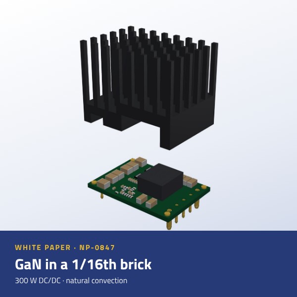
GaN in a 1/16th Brick: 300 W Non-Isolated DC/DC Conversion with Natural Convection
How gallium-nitride switching and CFD-driven heatsink design remove the fan from a standard-footprint point-of-load converter — for power, hardware and thermal design engineers
 Powering Your Challenge
Executive summary
Designers of 24 V and 48 V industrial systems are asked to deliver more power to their point-of-load rails while removing fans and keeping the board area they already have. The NP-0847 is Premium PSU’s answer to that request: a non-isolated synchronous buck converter in the industry-standard 1/16th-brick footprint (33.0 × 22.9 mm) that converts 9 V to 54 V into an adjustable 3.3 V to 15 V output, delivering up to 20 A and 300 W (405 W peak for 60 s) with efficiency of up to 98 % and natural-convection cooling [1].
Two design decisions make this possible:
- Gallium-nitride (GaN) power switches. Enhancement-mode GaN HEMTs have no reverse-recovery charge and much lower gate and output charge than silicon MOSFETs [4], so each switching edge wastes less energy. A GaN-optimised controller with smart near-zero dead-time control keeps the remaining transition losses to a minimum.
- A heatsink designed by simulation. A 3D conjugate CFD study of 40 candidate geometries replaced a commercial straight-fin profile with a 48-pin array. Heatsink-to-ambient thermal resistance fell by 17 % (13.6 K/W to 11.3 K/W) while aluminium mass fell by 40 % (24 g to 15 g), in the same footprint and height [3].
This paper explains the technology behind the module, its architecture and thermal design, and gives the information an engineer needs to design it in.
Download the full white paper (PDF)
Includes the complete specification tables, pinout, hole pattern, trim table and the recommended application circuit for the NP-0847.
1. The design challenge
1.1 Power density without forced air
Point-of-load converters fed from a 24 V or 48 V bus are common in industrial automation, communications and transport equipment. Fan-cooled designs reach high power density, but a fan adds acoustic noise, a filter to maintain and a wear-out component that often sets the service interval of the whole system. Removing it moves the entire thermal budget onto conduction and natural convection, which only works if the converter dissipates very little and the heat path to ambient is short.
1.2 Where silicon reaches its limits
In a hard-switched synchronous buck converter, silicon MOSFETs lose energy at every edge: charging and discharging output capacitance, overlapping voltage and current during the transition, and recovering the body diode of the synchronous switch. At 48 V input these losses scale with voltage and switching frequency. A designer is then forced to choose between a low switching frequency (large inductor, larger module) and a higher one (more loss, more heat). Removing the fan makes that trade-off harder.
Removing the fan moves the entire thermal budget onto conduction and natural convection — which only works if the converter dissipates very little and the heat path to ambient is short.
2. Why gallium nitride
2.1 Device-level advantages
GaN high-electron-mobility transistors (HEMTs) conduct through a two-dimensional electron gas instead of a silicon channel. For a power-conversion designer the relevant consequences are summarised in Table 1.
Table 1. GaN HEMT versus silicon MOSFET in a hard-switched half-bridge (qualitative, after [4]).
| Parameter | Silicon MOSFET | Enhancement-mode GaN HEMT |
|---|---|---|
| Reverse-recovery charge (Qrr) | Present (body diode) | Zero: no minority-carrier body diode |
| Gate charge (Qg) | Higher | Much lower: lower drive loss, faster edges |
| Output charge (Qoss) | Higher | Lower: lower turn-on loss in hard switching |
| Reverse conduction in dead time | Body-diode drop | Channel conducts with VF ≈ Vth + |VGS(off)|; keep dead time short |
| Consequence in a buck converter | Edge loss limits frequency and efficiency | Lower loss per edge; efficiency and density can both rise |
2.2 What this means in a synchronous buck
The absence of reverse-recovery charge removes the current spike and associated loss that occur when the high-side switch turns on against a conducting low-side device. Lower gate and output charge shorten the switching transition, which reduces overlap loss and allows a compact inductor without paying for it in efficiency. Because a GaN device in reverse conduction has a higher voltage drop than a silicon body diode [4], dead time must be kept as short as possible. The NP-0847 controller addresses this with smart near-zero dead-time control (section 3.2).
3. NP-0847 architecture
3.1 Power stage
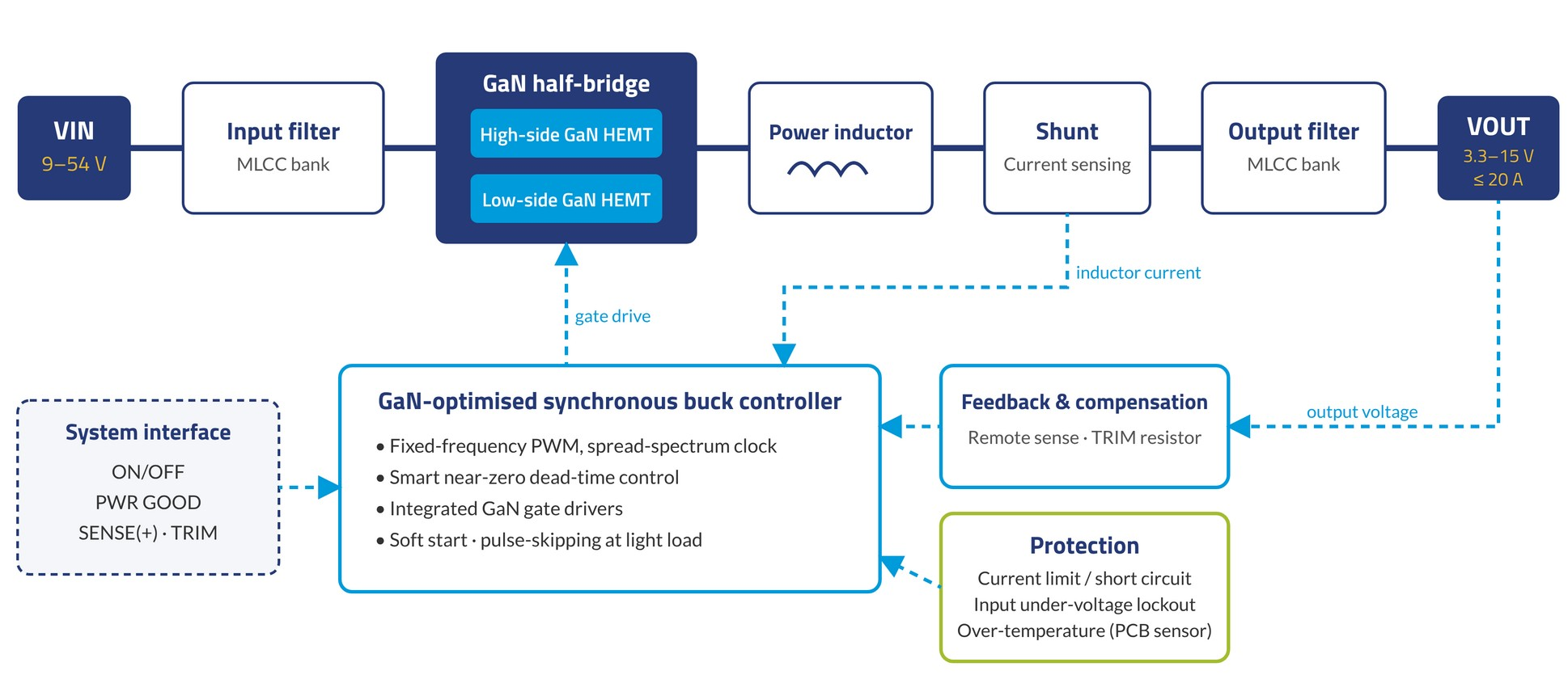
The power stage is a synchronous buck converter. A ceramic (MLCC) input filter supplies the pulsed input current close to a half-bridge of two 100 V-class enhancement-mode GaN HEMTs. The switch node drives a low-loss power inductor, followed by a precision current-sense shunt and a ceramic output filter. All power components sit under a common aluminium heatsink (Figure 2).
3.2 Control and timing
A synchronous buck controller designed for GaN switches drives both HEMTs through integrated gate drivers. The design uses:
- Fixed-frequency PWM at about 490 kHz with spread-spectrum modulation, which spreads conducted and radiated emission energy over a wider band.
- Smart near-zero dead-time control, which minimises the time either GaN device spends in reverse conduction.
- Pulse-skipping operation at light load, to keep light-load losses low.
- Soft start of about 6.7 ms, to limit inrush current into the output capacitance.
- Remote sense and resistor trim, so the regulation point can be placed at the load and the output set between 3.3 V and 15 V.
3.3 Sensing and protection
Inductor current is measured with a dedicated shunt rather than the inductor’s DC resistance. A shunt gives a sense signal that does not drift with inductor temperature, which makes short-circuit detection more consistent. The module provides current limiting for overload and short-circuit protection, input under-voltage lockout and an over-temperature shutdown driven by a temperature sensor mounted on the PCB (threshold above 100 °C) [1][2].
4. Thermal design
4.1 The natural-convection constraint
With no forced airflow, heat leaves the module through the pins into the host board and, mostly, from the heatsink to the surrounding air by natural convection and radiation. In natural convection the deciding factor is not fin area but whether cool air can reach the fin surface. A dense fin pattern that looks good on paper can trap air that is almost at metal temperature.
4.2 CFD-driven heatsink optimisation
Premium PSU ran a 3D conjugate CFD study (air and aluminium solved together, including convection and radiation) at the design dissipation of 5.19 W and 25 °C ambient [3]. Starting from a commercial straight-fin profile, 40 geometries were evaluated in five phases (starting profiles, interrupted fins, segmented fins, pins with gap equal to slot, and pin thickness), totalling 77 3D simulations. The workflow used open-source tools (OpenFOAM, gmsh, scikit-fem, ParaView and Python), with an AI agent automating geometry generation, simulation runs and result post-processing. The simulation model was validated against a measured prototype, with a deviation of +3.9 % [3].
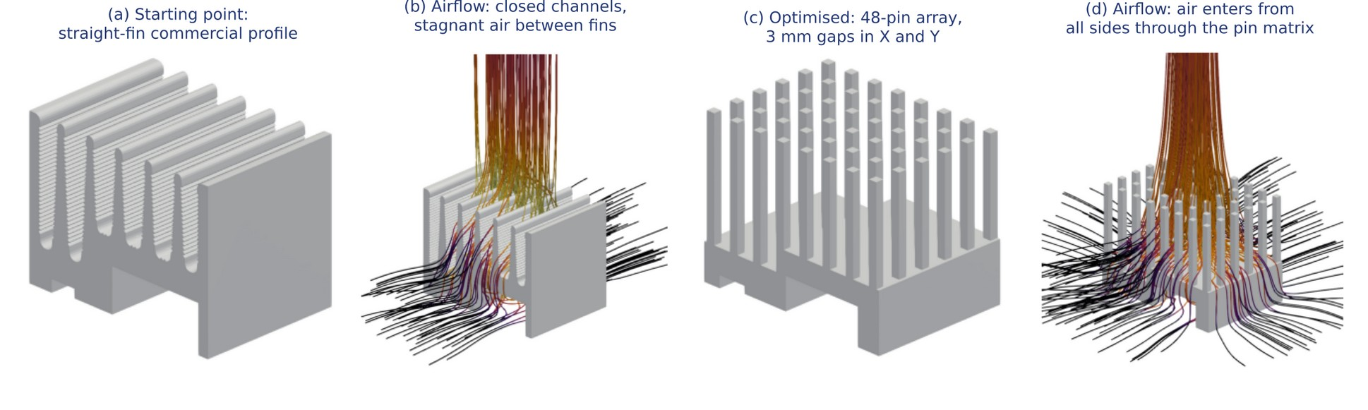
The selected design (Q4) is an array of 48 pins of 1.38 × 1.32 mm with 3 mm gaps in both directions. The commercial profile had closed channels fed only from the ends, so air stagnated and heated almost to metal temperature. In the pin array, air enters from every side and crosses the pin matrix; with thinner pins, more air paths fit and the air between them runs 1.5 K to 2 K cooler [3].
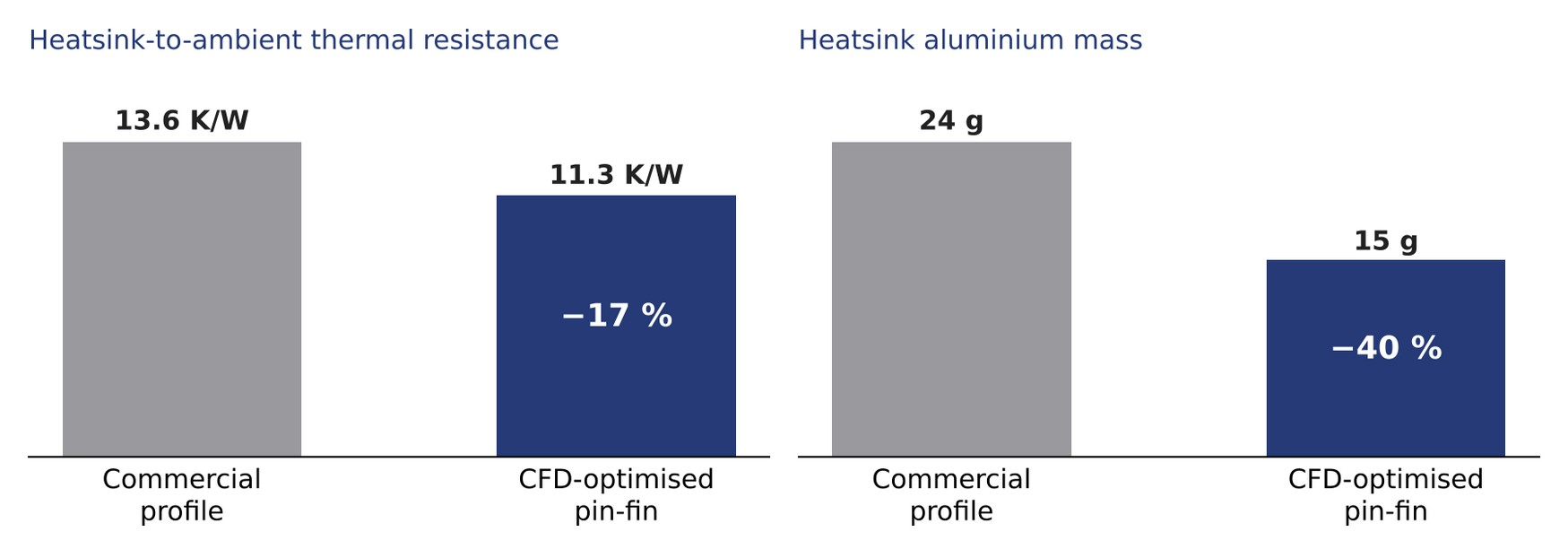
Table 2. Heatsink comparison at 5.19 W, 25 °C ambient, natural convection [3].
| Metric | Commercial profile | Optimised pin-fin (Q4) | Change |
|---|---|---|---|
| Thermal resistance, heatsink to ambient | 13.6 K/W | 11.3 K/W | −17 % |
| Heatsink temperature rise at 5.19 W | Reference | 12 K lower | −12 K |
| Aluminium mass | 24 g | 15 g | −40 % |
| Heat removed by convection / radiation | 67 % / 33 % | 71 % / 29 % | — |
Copper was evaluated and discarded. Conduction inside the heatsink is not the bottleneck: the temperature difference across the aluminium is only 2.5 K to 4 K. A copper base spreader gained 1.2 K; an all-copper heatsink gained 1.3 K but, unanodised, lost about 10 K through lower radiation and weighed 3.3 times more [3]. The production heatsink is anodised aluminium 6063-T5 [1].
5. Key specifications
Table 3. Main electrical, mechanical and environmental characteristics (preliminary, Gen1) [1].
| Parameter | Value | Unit |
|---|---|---|
| Input voltage, nominal | 24 / 48 | V |
| Input voltage range | 9 to 54 (VIN > VOUT) | V |
| Turn-on input voltage | 8 | V |
| Output voltage (set with RTRIM) | 3.3 / 5 / 12 / 15 | V |
| Output current, continuous / peak (60 s) | 20 / 27 | A |
| Output power at 15 V, continuous / peak | 300 / 405 | W |
| Efficiency | Up to 98 | % |
| Line / load regulation, max. | 0.5 / 1.3 | % |
| Ripple and noise (20 MHz BW), max. | 6 | %pp |
| Dimensions (W × D × H) | 33.0 × 22.9 × 30 | mm |
| Footprint | 1/16th brick, through-hole pins | — |
| Operating / storage temperature | −40 to 50 / −55 to 85 | °C |
| Cooling | Natural convection | — |
| Relative humidity | 5 to 95 | % |
| MTBF | > 10 | Mh |
Power density, counting the heatsink, is about 13 W/cm³ (300 W in 22.7 cm³), derived from the figures above.
6. Designing in the NP-0847
6.1 Pinout and footprint
Table 4. Pin functions [1].
| Pin | Function | Notes |
|---|---|---|
| 1 | VIN (+) | Input positive |
| 2 | ON/OFF | Remote enable |
| 3 | VIN (−) | Input return |
| 4 | VOUT (−) | Output return, power pin |
| 5 | PWR GOOD | Open-drain status; pull up externally (10 kΩ to 3.3 V) |
| 6 | TRIM | Output voltage adjustment |
| 7 | SENSE (+) | Remote sense at the load |
| 8 | VOUT (+) | Output positive, power pin |
6.2 Output voltage trim
The output is set by a single resistor RTRIM between TRIM and VOUT (−). Standard values are given in Table 5.
Table 5. Trim resistor for standard output voltages [1].
| VOUT (V) | RTRIM (kΩ) |
|---|---|
| 3.3 | Open |
| 5 | 11.3 |
| 12 | 2.15 |
| 15 | 1.58 |
6.3 Typical application circuit
- Place a 100 µF input capacitor between VIN (+) and VIN (−), close to the module.
- Place 0.1 µF ceramic and 22 µF capacitors at the output. Connect SENSE (+) at the load for best regulation.
- Pull PWR GOOD up to the logic rail (10 kΩ to 3.3 V in the reference circuit).
- The module has no reverse-polarity protection: add it externally if the input can be reversed in the application.
- Keep VIN above VOUT; minimum operating input is 9 V and the module turns on at 8 V.
- Allow free vertical airflow around the heatsink: the thermal design relies on air entering the pin array from all sides.
7. Safety, environment and reliability
- Safety: designed according to IEC 62368-1, pollution degree PD2, overvoltage category OV2 [1].
- Environmental compliance: RoHS according to Directive (EU) 2015/863 and REACH [1].
- Reliability: predicted MTBF above 10 million hours [1].
- Protection: current limiting for overload and short circuit, input under-voltage lockout, over-temperature shutdown.
Conclusion
The NP-0847 shows that GaN switching and simulation-driven thermal design together let a 1/16th-brick converter deliver 300 W without a fan. GaN removes reverse-recovery loss and shortens every switching edge; near-zero dead-time control keeps reverse-conduction loss low; and a CFD-optimised pin-fin heatsink takes the remaining heat to ambient with 17 % lower thermal resistance and 40 % less aluminium than a catalogue profile. For the system designer, the result is a standard-footprint module with the control and protection functions expected of a brick, and one less moving part in the system.
To evaluate the NP-0847 in your application, contact the Premium PSU engineering team through www.premiumpsu.com.
Download the full white paper (PDF)
Includes the complete specification tables, pinout, hole pattern, trim table and the recommended application circuit for the NP-0847.
References
- [1] Premium PSU, CA-762-C Datasheet NP-0847 (Gen1), ed. 3, 2026-08-05.
- [2] Premium PSU, Schematic SCH-NP0847 – Buck Converter BRICK, rev. B, 2026-10-14 (internal).
- [3] Premium PSU, GaN heatsink: from commercial profile to CFD-optimised design, internal study (OpenFOAM), 2026 (available on request).
- [4] GaN Systems, GN001 Application Guide: Design with GaN Enhancement Mode HEMT, 2018-02-28. https://gansystems.com
- [5] IEC 62368-1, Audio/video, information and communication technology equipment – Part 1: Safety requirements.
- [6] Commission Delegated Directive (EU) 2015/863 amending Annex II to Directive 2011/65/EU (RoHS).