
Tag Archive for: RAMS
 Whitepapers
White paper – 40+ Year Reliability in Critical Power Electronics
40+ Year Reliability in Critical Power Electronics: The Premium SA Approach
Physics-of-Failure, DFR methodology, RAMS metrics and PHM — for directors of engineering, procurement and operations

Born in Barcelona, Powering the World
Introduction: From Unit Price to Total Cost of Ownership
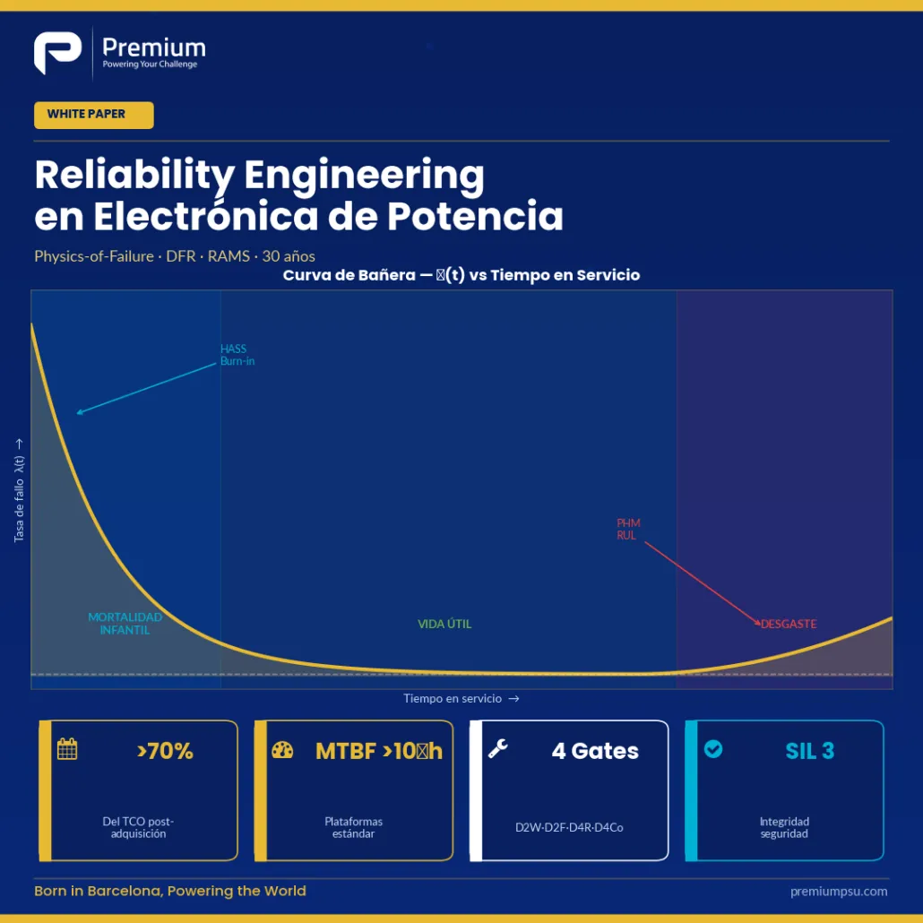
In critical infrastructure — rolling stock, electrical substations, signalling systems, continuous-process plants — the cost of one hour of unavailability far exceeds the price of any electronic converter. Over the last decade, the fraction of total cost of ownership attributable to the acquisition price has fallen below 30% in railway and substation grid applications; the remaining 70% is split between energy consumed, scheduled maintenance, spare parts and, above all, unavailability.
The result is that the purchase decision has migrated from unit price to total cost of ownership. The real question is no
longer “how much does it cost?” but “how long will it last and how will you prove it?”
1. Why Power Electronics Fails — The Physical Mechanisms
Electronic components do not fail randomly: they fail through identifiable, modellable and predictable physical mechanisms. The Physics-of-Failure (PoF) methodology — which Premium SA adopts as primary reference, as opposed to the outdated MIL-HDBK-217F — classifies these mechanisms into four families:
1. Thermo-Mechanical Mechanisms
Dominant in power modules (IGBT, MOSFET, SiC). Every thermal cycle causes materials with different coefficients of thermal expansion (CTE) to expand and contract at different rates, accumulating plastic deformation in solder joints and bond wires.
- Solder fatigue: Coffin-Manson model: Nf ∝ ΔTj−n with n ≈ 5–7. Increasing Rth(j-c) → vicious circle of rising Tj and accelerating degradation
- Wire-bond lift-off: Main cause of wear-out failure in traction IGBT modules. Each lost wire increases current in remaining ones, accelerating the next failure
2. Electrical & Dielectric Mechanisms
Active semiconductors age through electrical causes, with no need for thermal cycles. Degradation accumulates during normal operation.
- TDDB: Gate oxide traps accumulate until resistive conduction path forms. Arrhenius model with electric field accelerator
- Electromigration: Black model with J² as main variable. Opens voids or creates shorts in metallisation traces
- Hot Carrier Injection (HCI): Particularly relevant in fast-switching SiC and GaN transistors
- NBTI/PBTI: Gradual transconductance gm reduction under bias at high temperature
3. Chemical & Environmental Mechanisms
Humidity, contaminants, salts and radiation present in any real installation.
- Corrosion and electrochemical migration: Dendrite formation (whisker effect) causing intermittent shorts. Peck model (humidity × temperature)
- Radiation-induced errors (SEU): Cosmic ray neutrons and alpha particles causing Single Event Upsets in memory cells. Mitigated by design: ECC, watchdogs, logical redundancy
4. Mechanical Mechanisms
In railway applications under EN 61373 (category 1B body-mounted), equipment absorbs 5–50 m/s² of random vibration over full life. Critical points: solder joints of heavy components (electrolytics, ferrites, transformers) and connectors. Design control: first mechanical PCB frequency clearly above dominant excitation range (>75 Hz).
2. The Bathtub Curve — Each Phase Calls for a Different Technique
Electronic components exhibit three recognised phases: infant mortality (high initial failure rate from latent manufacturing defects), useful life (low and approximately constant rate), and wear-out (rising rate from accumulation of physical mechanisms). A mature DFR process attacks all three simultaneously.
| Technique | Phase Addressed | When Applied | Premium SA Standard |
|---|---|---|---|
| HALT (Highly Accelerated Life Testing) | Design margin discovery | Design phase on prototypes | Combined temperature + vibration stresses beyond specification limits |
| HASS (Highly Accelerated Stress Screening) | Latent manufacturing defects | Production screening | Stress levels just below operating limit; 100% of production units |
| Burn-in | Infant mortality (left tail) | Post-production, pre-delivery | 4 h per unit at +60 to +80 °C; extendable to 8 h for long-interval programmes |
3. RAMS — The Contractual Language of Reliability
RAMS stands for Reliability, Availability, Maintainability, Safety — the four metrics with which a railway operator or grid DSO measure equipment suitability over its useful life. EN 50126 is the framework standard; EN 50128 and EN 50129 cover software and functional safety respectively.
Reliability
R(t) — probability of surviving to time t. Expressed as MTBF = 1/λ for exponential distribution, or by Weibull parameters (β, η) for wear-out phases. Premium SA calculates MTBF by PoF, not by parts-count (MIL-HDBK-217F).
Availability
A = MTBF / (MTBF + MTTR). For a substation converter with MTBF = 500,000 h and MTTR = 4 h: A ≈ 99.9992%. The key lever is not only increasing MTBF but also reducing MTTR.
Maintainability
Design levers: LRU architecture (front access, two captive screws, keyed connectors), built-in telemetry and self-test, RUL (Remaining Useful Life) estimation via PHM, and 40+ year spares continuity with quarterly obsolescence review.
Safety — EN 50128 / 50129
SIL (Safety Integrity Level) per IEC 61508. PFD (Probability of Failure on Demand) for standby safety functions. SIL 3–4 requires: redundancy, periodic self-test, MC/DC software coverage metrics, formal methods. Premium SA D4Co-SW methodology aligned with EN 50128.
4. The Premium SA DFR Process — Four Sequential Gates
The Design for Reliability (DFR) methodology — originated at the Center of Reliable Power Electronics (CORPE, Aalborg University) and adopted as an internal standard at Premium SA — structures development in four sequential gates with quantitative exit criteria:
| Gate | Objective | Key Activities | Exit Criterion |
|---|---|---|---|
| D2W (Design to Work) | Functional specification | Mission profile definition, requirements capture, architecture selection | Signed mission profile + functional test pass |
| D2F (Design to Function) | Derating and PoF analysis | Tj_max ≤ 80%, Vop ≤ 80%, thermal simulation, stress analysis | All derating targets met; no RPN > 80 open |
| D4R (Design for Reliability) | FMEA, FTA, HALT | FMEA bottom-up + FTA top-down; HALT protocol; Coffin-Manson solder analysis | RPN > 100 blocked; HALT limits documented; MTBF target verified |
| D4Co (Design for Compliance) | Qualification and FRACAS | HASS production screening; burn-in; EMC pre-compliance; EN 50155/EN 61373 qualification | All certifications obtained; FRACAS activated; customer RAMS deliverables signed |
5. FMEA, FTA and the Analytical Hierarchy
Once derating is established, reliability engineering identifies and mitigates dominant failure modes through three complementary analyses:
- FMEA/FMECA (Failure Mode and Effects Analysis): Bottom-up. RPN = Severity × Occurrence × Detection (1–10 scale). At Premium SA, any RPN >80 triggers a documented action plan; RPN >100 blocks the D4Co gate.
- FTA (Fault Tree Analysis): Top-down. Decomposes boolean combinations (AND/OR gates) that may cause system fault. Quantifies impact of redundancies; allows calculation of system-level MTBF.
- ETA (Event Tree Analysis): Inductive. Models scenarios and responses derived from a single initiating event. Useful for evaluating fault propagation in multi-state systems.
6. Keeping Reliability in Service — PHM, FRACAS and Lean Reliability
PHM — Prognostics and Health Management
The active technical frontier today is the transition from fixed-schedule preventive maintenance towards maintenance based on actual condition. In Premium SA converters:
- Real-time Tj estimation of semiconductors from Vce_sat and current, with case-temperature compensation
- Cumulative power-cycle counting with associated ΔTj, to predict RUL (Remaining Useful Life) by PoF models
- ESR monitoring of capacitors by ripple analysis
- Periodic export of operating data over communication bus to the operator’s supervisor, with P-F (potential-functional) profile
FRACAS — The Continuous-Learning Loop
Failure Reporting, Analysis and Corrective Action System: every field return is analysed at the appropriate level — LRU, board, component — root cause is identified, and the corrective action is propagated to design and production. The consequence is that the population of installed equipment improves over time rather than degrading. The problem detected in unit #150 is prevented in unit #151.
About Premium SA — Premium SA is a Barcelona-based manufacturer of power electronics converters for railway, industrial and energy applications. Founded in 1981, with more than 900 standard product designs and over 40 years of operational experience, Premium SA supplies DC/DC converters, DC/AC inverters, AC/AC frequency converters, battery chargers, rectifiers and UPS systems from 50 W to 72 kW. All products are designed and manufactured at the Premium SA plant in Barcelona, with capability for EN 50155, EN 50121-3-2, EN 45545-2 and EN 61373 certification. Premium SA serves OEMs and system integrators across Europe through direct sales and a network of specialist distributors — ELIPSE (Benelux), Elma Electronic (Switzerland), RELEC Electronics (United Kingdom), DACPOL (Poland and Central Europe) and ANDA-OLSEN (Scandinavia).
Premium SA · Barcelona, Spain · info@premiumpsu.com · +34 932 232 685 · www.premiumpsu.com
 Application Notes
Advances in Power Electronics: Reliability and RAMS
Advances in Power Electronics: Reliability and RAMS
From the potentiometer to digital and laser trimming, from the electrolytic capacitor to software-based ripple control — a roadmap to 40-year reliability in critical infrastructure and railway
Executive Summary
Industrial and railway power electronics is going through a quiet but decisive transition: the replacement of electromechanical components and manual trimming techniques with solid-state architectures and deterministic calibration processes. Three levers drive this transition — the progressive elimination of the potentiometer, the reduction or elimination of the electrolytic capacitor, and the introduction of laser trimming on thick-film technology as the precision adjustment method in production. Each one targets a specific failure mechanism that historically limited converter service life; combined, they explain why a well-engineered unit today can be committed to an MTBF an order of magnitude higher than its fifteen-year-old predecessor at the same power rating.
This article walks through the three levers, ties them together with the Design for Reliability (DFR) methodology applied at Premium SA — mission profile, derating, FMEA, HALT/HASS, burn-in, FRACAS — and connects the result with the RAMS requirements of railway (EN 50126 / EN 50128 / EN 50129) and of critical grid infrastructure. The thesis is simple: 40-year reliability cannot be bought, it has to be designed; and the technological advances described here are the tools that make such a design viable.
1. The Paradigm Shift: From Reliability as Outcome to Reliability as Design Decision
For decades, the reliability of a power converter was measured after the fact. A unit was designed against a functional specification, manufactured, delivered, and the field failure rate was observed in service. If the number was unacceptable, the design was reworked. This “test-and-fix” approach has a well-known structural cost: correcting a reliability problem scales roughly 1× at schematic stage, 10× at layout, 100× at qualification testing, and grows by several additional orders of magnitude when the issue surfaces in a deployed fleet. The economics simply do not work in sectors with 30-year vehicle or substation lifecycles.
Design for Reliability (DFR), originated at the Center of Reliable Power Electronics (CORPE, Aalborg University) and adopted as the internal standard at Premium SA, inverts this order: reliability is set as a quantitative target at project kickoff — mission profile, target MTBF, service life, environmental conditions, thermal cycling — and the entire development process is structured to meet that number. The associated paradigm shift is the migration from handbook statistical models (MIL-HDBK-217F) toward a Physics-of-Failure (PoF) approach, grounded in the actual physical failure mechanisms: thermal fatigue of solder joints and wire bonds (Coffin-Manson), electrolyte evaporation under Arrhenius, electromigration, corrosion, mechanical fatigue of fasteners.
2. Goodbye to the Potentiometer: Digital Adjustment and Laser Trimming
2.1 The potentiometer as a concentrator of failure modes
The mechanical potentiometer has been the standard component for production calibration and field maintenance adjustments in power converters for half a century. Its appeal is obvious: it allows fine tuning of an analogue value (a voltage reference, a protection trip point, a gain) without changing components or reprogramming anything. But that very flexibility hides a concentration of failure mechanisms unmatched by any other passive component on the converter: mechanical wear of the resistive track; sensitivity to vibration (EN 61373 Cat. 1B); sensitivity to humidity and contamination; single point of intermittent failure via the wiper contact; and human risk in the adjustment — any manual field intervention is an opportunity to introduce an untraced calibration error.
The question is not whether a potentiometer will fail, but when. In a unit with a 30-year service life and a railway or substation mission profile, the answer is invariably “before the end”.
2.2 Replacement strategy 1 — digital potentiometer and parametric calibration
The first replacement strategy moves the adjustment to the digital domain. The analogue reference no longer comes from a trim resistor divider but is generated by software from a parameter stored in the microcontroller’s non-volatile memory or in an external EEPROM. Calibration is performed once in production, on a calibrated and traceable test bench, and is recorded against the unit’s serial number, operator, date and process signature.
| Characteristic | Mechanical potentiometer | Parametric digital calibration |
|---|---|---|
| Adjustment mechanism | Wiper sliding on resistive track | Read parameter from EEPROM/Flash |
| Temporal stability | Cumulative wear, vibration, humidity | Only DAC/MCU drift (ppm/°C) |
| Traceability | None beyond manual procedure | Digital log signed by serial number |
| Maintenance risk | Misalignment by human intervention | Protected calibration (digital signature) |
| Dominant failure mode | Intermittent wiper opening | MCU failure or EEPROM corruption |
| Typical function MTBF | < 50,000 h in harsh environments | > 500,000 h (silicon-limited) |
2.3 Replacement strategy 2 — laser trimming on thick film
Thick-film technology has matured to make laser trimming a standard industrial process. Modern resistive pastes (RuO₂ and advanced ceramic compounds) provide stable resistors up to 300 °C continuous operation, with temperature coefficients below ±25 ppm/°C in precision grades. Components produced this way are surge-resistant, mechanically robust and their value does not drift over time under normal operating conditions.
2.4 When to choose each strategy
| Function to be set | Preferred strategy | Reason |
|---|---|---|
| OVP/OCP/OTP trip points | Digital calibration | Mandatory traceability; RAMS audit |
| Control-loop gain | Deterministic design (no trim) | No post-design adjustment at all |
| Internal voltage reference | Laser-trimmed precision resistor network | Absolute stability without firmware involvement |
| Shunt current sensor | Laser-trimmed integrated resistor | 0.1 % tolerance with no temporal variation |
| Instrumentation amplifier gain | Laser-trimmed R2R network, IC-integrated | Current industry standard |
| Per-unit offset compensation | One-shot digital calibration in production | Covers natural silicon dispersion |
| Field-variable operating point | Signed digital parameter | Zero physical manual intervention |
The practical conclusion is that in a modern Premium SA control board there should be no physical potentiometer at all. Factory adjustments are laser or digital; field adjustments are digital-only, protected by signature; control loops are deterministic by design.
3. Reducing and Eliminating the Electrolytic Capacitor
3.1 The electrolytic as the Achilles heel of the DC bus
If the potentiometer is the Achilles heel of calibration, the aluminium electrolytic capacitor is the Achilles heel of the DC bus. It is typically the component that fixes the service-life ceiling of a power converter, because it combines five awkward properties: service life intrinsically limited by electrolyte evaporation (life ÷2 every +10 °C); ESR growing with ageing; capacitance decreasing to ~80 % at end-of-life; sensitivity to ripple current (Pdis = Iripple² × ESR → self-heating → accelerated ageing); and mechanical sensitivity requiring rigid restraint under EN 61373.
3.2 Premium SA strategy — long-life 105 °C capacitors
The first line of defence, when an electrolytic is unavoidable due to capacitance density, is aggressive part selection. Premium SA standardises on aluminium capacitors rated to 105 °C (some ranges to 125 °C in critical applications) with manufacturer-declared service life of 8,000 to 12,000 hours at maximum temperature — equivalent, by Arrhenius, to over 100,000 hours when operated at 50 °C. Combined with the Premium SA derating policy — Vop ≤ 80 % of Vrated, Iripple_real ≤ 80 % of Iripple_rated, Ta_cap < 85 °C in worst case — this pushes the ageing curve well below the product’s service-life horizon.
But “pushing” is not “eliminating”. As long as there is an electrolytic on the DC bus, there is a wear-out component that defines the slope of the bathtub curve at end of life.
3.3 Why digital ripple control changes the rules
| Aspect | DC bus with electrolytics | DC bus with film + digital control |
|---|---|---|
| Dominant component | Aluminium electrolytic 105 °C / 12,000 h | Polypropylene film, > 200,000 h |
| Dominant failure mechanism | Electrolyte evaporation (Arrhenius) | No significant wear-out mechanism |
| Thermal sensitivity | Life ÷2 every 10 °C | Minimal across operating range |
| Capacitance with ageing | Drops to 80 % at end of life | No significant drop |
| ESR evolution | Grows ×2 by end of life | Stable across full service life |
| DC-bus function MTBF | Limited by the electrolytic | Limited by semiconductors |
| TCO | Low BOM, high service cost | Higher BOM, lower service cost |
3.4 The measurable impact — MTBF, MTTR, reliability
Removing the electrolytic from the DC bus simultaneously moves all three metrics that matter in critical infrastructure. MTBF rises — we have observed typical 5× to 10× improvements in converters where the electrolytic was the limiting factor. MTTR drops because the LRU is replaced less frequently and the spare-parts catalogue is simplified. Reliability R(t) approaches 1 asymptotically over the full 30-year horizon, instead of degrading in the last 10 years due to electrolytic wear-out. These effects are particularly valuable where downtime carries contractual cost: an electrical substation where a fault triggers DSO penalties, or a rolling-stock fleet where a withdrawal from service breaks the operator’s timetable.
4. Design for Reliability — the Methodology that Ties the Advances Together
The two technological levers above are necessary but not sufficient conditions. 30-year reliability also requires a development process that integrates and verifies them. The Premium SA DFR methodology structures the design across four sequential gates — D2W (Design to Work), D2F (Design to Function), D4R (Design for Reliability) and D4Co (Design for Compliance) — each with quantitative exit criteria.
4.1 Mission profile and derating as non-negotiable input
The first artefact of any Premium SA project is the mission profile: maximum and minimum ambient temperature, daily thermal cycles, cyclic humidity, altitude, vibration, expected number of starts over the service life, frequency of S2 supply-interruption events. Without this input, no PoF calculation has any meaning. With it, derating decisions become quantitative.
| Component family | Premium SA derating rule | Physical justification |
|---|---|---|
| Power semiconductors | Tj ≤ 80 % of Tj_max (≤ 125 °C Si, ≤ 150 °C SiC) | Coffin-Manson on wire bonds: Nf falls as (ΔTj)^β |
| Aluminium electrolytics | Vop ≤ 80 % Vrated, Iripple ≤ 80 % rated | Arrhenius law on electrolyte evaporation |
| MLCC capacitors | Vop ≤ 50 % Vrated | Capacitance loss vs DC bias on X5R/X7R |
| Resistors | Pop ≤ 60 % Prated, Vop ≤ 80 % Vrated | Intra-component insulation |
| Connectors | I ≤ 70 % Irated per contact | Contact heating under fatigue |
| Insulation (creepage/clearance) | ≥ 1.5× minimum per EN 50124-1 | Margin against long-term contamination |
4.2 FMEA, FTA and the failure-mode hierarchy
Once derating is set, reliability engineering concentrates on identifying and mitigating the dominant failure modes through two complementary analyses. FMEA (Failure Mode and Effects Analysis) works bottom-up: for each component and each interface, possible failure modes, their causes and their effects are enumerated, with a Risk Priority Number assigned (RPN = Severity × Occurrence × Detection, 1–10 scale). At Premium SA, any RPN > 80 triggers a documented action plan, and RPN > 100 blocks the D4Co gate. FTA (Fault Tree Analysis) works top-down: it starts from the system failure and decomposes the Boolean combinations (AND/OR gates) that can cause it, allowing the impact of redundancies to be quantified and improvements to be prioritised by sensitivity factor.
4.3 The bathtub curve — each phase calls for a different technique
| Bathtub phase | Dominant cause | Control strategy |
|---|---|---|
| Infant mortality (0–500 h) | Latent manufacturing defects: cold solder, contamination, assembly errors | HALT in design + HASS/burn-in in production + 100 % AOI/ICT |
| Useful life (500–50,000 h) | Random events: overvoltage, ESD, mains transients | Protections (OVP/OCP/OTP), derating, preventive FMEA |
| Wear-out (> 50,000 h) | Accumulated damage: thermal fatigue, electrolyte degradation, corrosion | Low Tj_max, reduced ΔTj, eliminate electrolytics, condition monitoring |
4.4 HALT, HASS and burn-in — what each one does
These three techniques are often confused, and they tackle different problems at different moments. HALT (Highly Accelerated Life Testing) is a limit-exploration test in the design phase: combined stresses (temperature + vibration) are progressively applied beyond the specification, until the operational and destruct limits of the product are found. It is not a qualification test, it is a discovery test — the output is the knowledge of how much margin we hold. HASS (Highly Accelerated Stress Screening) is a production-phase variant, with stress levels chosen just below the operational limit, used to detect latent manufacturing defects without consuming the product’s service life. Burn-in operates the product under controlled temperature (typically +60 to +80 °C) and load for several hours to screen the infant-mortality phase. Premium SA standardises 4 h of burn-in per unit, extended to 8 h on programmes with long maintenance intervals.
The three are complementary: HALT explores; HASS screens in production; burn-in cuts the left tail of the bathtub curve. Applied together, the failure rate during the first year in service drops to a fraction of the value without these techniques.
5. The Other Component that Also Ages — the Software
Any modern converter with digital calibration, predictive ripple control, complex protections and communication with the network supervisor carries firmware of growing complexity. From the function-reliability standpoint, this firmware is just another component of the system — and like any other component, it can be the root cause of a failure that compromises availability. The difference is that software does not age physically, but confidence in it erodes if there is no disciplined verification and validation process.
5.1 V-Model and EN 50128 as the framework for railway firmware
The reference standard for railway-application software is EN 50128, part of the EN 5012x family (railway RAMS). Its central element is the V-Model: each level of specification (system requirements, software requirements, architectural design, module design, code) corresponds to a verification level (unit testing, integration testing, system testing, acceptance testing). Each SSIL (Software Safety Integrity Level, levels 1 to 4 plus Basic Integrity) imposes mandatory techniques: formal reviews, static analysis, specific coverage metrics.
| SSIL level | Typical converter application | Mandatory EN 50128 techniques |
|---|---|---|
| Basic Integrity | Functions unrelated to safety | Code review, functional testing |
| SSIL 1-2 | Cabin auxiliaries, monitoring | MISRA C static analysis, unit-test I/O coverage |
| SSIL 3 | Traction converters not brake-critical | MISRA + decision coverage + timing analysis |
| SSIL 4 | Active safety functions (e.g. brake inhibition) | MC/DC coverage, formal models, redundancy |
5.2 MISRA C, MC/DC and why they matter
MISRA C:2012 is the de facto standard for embedded firmware in C in critical systems. Its 143 rules (16 mandatory, 111 required, 16 advisory) cover language patterns that have historically been a source of defects: pointer aliasing, implicit conversions, undefined behaviour, dynamic memory management. Applying MISRA with static analysis (PC-lint, Coverity, Polyspace) removes a whole class of defects before execution. MC/DC (Modified Condition/Decision Coverage) is the most demanding coverage criterion routinely applied in certification: it requires that each individual condition within a Boolean decision independently affects the result of the decision. For a decision with n conditions, the minimum number of MC/DC tests is n+1, against the 2n required by combination coverage.
5.3 HIL and firmware verification on real hardware
The technique that closes the verification loop is HIL (Hardware-in-the-Loop). The firmware runs on the real microcontroller, but the input signals (voltage, current and temperature sensors) are synthesised by a real-time simulator that emulates the behaviour of the DC bus, the transformer, the motor or the load. This allows thousands of scenarios to be executed — including sensor failures, mains transients, short-circuits — with no physical risk to the equipment or to the test bench. A well-designed HIL programme catches hardware/software integration defects that no unit test could capture.
6. RAMS — the Metric that Ties Everything Together
RAMS stands for Reliability, Availability, Maintainability, Safety — the four metrics a railway operator or a grid DSO uses to judge the suitability of a unit across its service life. EN 50126 is the framework standard; EN 50128 and EN 50129 cover software and functional safety respectively.
6.1 The full R-A-M-S quadrant
| Metric | Operating definition | Dominant design lever |
|---|---|---|
| Reliability | Probability of fault-free operation across t | Component selection, derating, wear-out elimination |
| Availability | Fraction of time the system is operational | MTBF + MTTR; redundancy where applicable |
| Maintainability | Ease and speed of diagnosing and repairing | LRU design, telemetry, FRACAS, parts continuity |
| Safety | Absence of unacceptable risk | FTA, safe failure modes, software SSIL, redundancy of critical functions |
6.2 FRACAS — the continuous learning loop
FRACAS (Failure Reporting, Analysis and Corrective Action System) is the process by which every field return is analysed at the appropriate level — LRU, board, component — the root cause is identified, and the corrective action is propagated back to design and production. Premium SA runs FRACAS as a closed loop between Quality, Aftersales and R&D. The consequence is that the fleet population improves over time, rather than degrading: the issue detected in unit #150 is prevented in unit #151.
6.3 PHM and the move to predictive maintenance
The active technical frontier today is PHM (Prognostics and Health Management): the transition from fixed scheduled maintenance toward maintenance based on the actual condition of the equipment. In Premium SA converters we progressively implement: real-time Tj estimation of power semiconductors from Vce_sat and current; cumulative power-cycle counting with the associated ΔTj to predict RUL (Remaining Useful Life) via PoF models; capacitor ESR monitoring by ripple analysis; and periodic export of operational data to the operator’s supervisor over the communications bus. The result is that the operator no longer has to choose between excessive preventive maintenance and late corrective maintenance — the equipment reports how much life is left.
7. Synthesis: the Concrete Levers that Make 30-Year Reliability Viable
| Technological lever | Failure mode it removes | RAMS effect |
|---|---|---|
| Eliminating the potentiometer (digital + laser) | Wiper wear, vibration/humidity drift, human error in maintenance | Raises R, lowers MTTR |
| Reducing/eliminating the electrolytic (digital control + film) | Arrhenius wear-out of electrolyte | Raises MTBF 5–10×; flattens bathtub tail |
| Selection of 105–125 °C long-life electrolytics (where unavoidable) | Accelerated Arrhenius ageing of the limiting component | Pushes wear-out beyond the 30-year horizon |
| DFR + mission profile + derating | Random faults and overstress in the useful-life phase | Raises R in the central area of the curve |
| HALT in design + HASS/burn-in in production | Latent manufacturing defects (infant mortality) | Flattens the left tail of the bathtub curve |
| Software V&V (V-Model, MISRA, MC/DC, HIL) | Systematic firmware faults | The component that closes the case for a 30-year claim |
| LRU design + FRACAS + 30-year parts continuity | High MTTR and mid-life obsolescence | Raises A via the MTTR lever; protects the full lifecycle |
| PHM + condition monitoring | Inefficient maintenance (excessive preventive or late corrective) | Optimises total cost of ownership |
About Premium PSU — With over 40 years of experience, Premium SA designs and manufactures custom power converters in Barcelona for railway, energy, industrial, data center and defence applications.
 Application Notes, Data Center
Engineering the Power Stack for AI Data Centers
Engineering the Power Stack for AI Data Centers
Custom mission-critical power electronics for AI factories, HPC clusters and hyperscale data centres — >97% efficiency, >1 kW/L density, MTBF >10⁶ h
Three barriers between AI and reliable power
Generative AI and HPC workloads are creating unprecedented demand for power infrastructure. Rack densities are growing 10× in five years. Hyperscale operators demand Titanium-class efficiency. AI factories tolerate zero downtime. Three barriers define the engineering problem — and all three must be solved simultaneously.
Efficiency: >97%
Titanium-class efficiency at every conversion stage. Every percentage point saved at 1 MW means 10 kW less heat — and a real capex reduction in cooling infrastructure.
Power density: >1 kW/L
Rack density is growing from 10–15 kW/rack to 200+ kW/rack by 2028. WBG semiconductors (SiC, GaN) and planar magnetics are the only viable path to meet these targets.
Reliability: >10⁶ h MTBF
AI factories run 24/7 with zero tolerance for downtime. Physics-of-Failure design, RAMS analysis and thermal budget management are non-negotiable engineering requirements.
Mission-critical power engineering, now for AI infrastructure
Premium PSU is not entering the data centre market from zero. We are transferring over 40 years of engineering experience from railway traction (EN 50155, EN 61373), defence and grid infrastructure — sectors where failure is simply not an option — into a market that now demands exactly those same standards.
| Capability | Focus | What it means in practice |
|---|---|---|
| WBG semiconductors | SiC · GaN · Ga₂O₃ | Baliga FOM-driven device selection. SiC for high-blocking-voltage stages; GaN for high-frequency switching. Gate-driver design, EMI management and long-term reliability qualification in-house. |
| Thermal engineering | RAMS · phonon engineering | 55% of power electronics failures are thermally driven. We apply Coffin-Manson fatigue modelling, thermal budget allocation and advanced substrates (Si₃N₄, AlN) from prototype to production. |
| Digital control | FPGA · SoC · predictive control | High-bandwidth digital loops, model-based design (MiL→SiL→HiL). Real-time telemetry via PMBus, SNMP, Modbus and REST. Full DCIM integration out of the box. |
| Passive components | Magnetics · capacitors | Custom inductors and transformers with nanocrystalline/ferrite cores. Elimination of electrolytic capacitors in critical paths — historically 35% of field failures. |
CPD-Ready 125V DC Kit — from pilot to hyperscale
Turn-key power infrastructure for AI compute, designed for native OCP Open Rack v3 (ORv3) architecture and full DCIM integration. Available in four power configurations — 20, 40, 60 and 72 kW — to match rack density targets from edge to AI factory scale.
- N+1 redundancy: hot-swap modules with seamless failover — zero downtime during maintenance windows.
- OCP ORv3 compliant: native support for the Open Compute Project Open Rack v3 architecture.
- Unified telemetry: SNMP / Modbus / REST — full integration with DCIM platforms.
- Pre-validated EMC: CE, IEC 62368-1, UL ready — integrated EMC-checked BOM.
- WBG switching stages: SiC-based conversion for >95% efficiency at full load.
- Co-development ready: custom configurations of voltage, form factor, firmware and interface.
Standard catalogue models for data centre architecture
| Model | DC application | Key adaptation | Power range |
|---|---|---|---|
| CKR-3600 | Modular 48V front-end rectifier | ≥97% eff., OCP ORv3 hot-swap, PMBus/SNMP | Up to 3.6 kW/module |
| CRS-2000 / 3000 | DC-DC mid/high power (48V ↔ 380V) | PMBus telemetry, >1 kW/L density | 2–3 kW |
| ODS-1500 / 3000 | AC/DC isolated front-end, edge | Modular scaling, >95% peak, Titanium | 1.5–3 kW |
| EPS-200 / 2000 | DC UPS — edge and critical rooms | Li-ion modular, bidirectional, SNMP | 200 W – 2 kW |
| ODX / OVX-6000 | Resilience inverters and microgrid | 19″ rack, remote control + telemetry | Up to 6 kW |
Over 40 years engineering power where failure is not an option
Our engineering credentials come from the most demanding industrial applications. Every methodology we apply in AI data centre projects — Physics-of-Failure, RAMS, thermal budget analysis — has been validated under real-world mission-critical conditions:
- Railway traction and high-speed rail: converters and inverters qualified to EN 50155, EN 61373 and EN 45545-2, including cold-start designs for −40 °C arctic operation and cross-border certification management. The same thermal and reliability design methodology applies to AI rack power.
- Urban rail systems: full RAMS analysis and EN 61373 vibration qualification, with rapid prototyping cycles.
- Grid infrastructure: modular inverter deployments across distribution networks. Grid-grade reliability and modular architecture are directly applicable to DC microgrid and AI campus designs.
Power electronics for AI data centres — technical Q&A
What power electronics does Premium PSU offer for AI data centres?
Premium PSU offers custom power electronics for AI data centres, including the CPD-Ready 125V DC Kit (20/40/60/72 kW, OCP ORv3 compliant), modular 48V rectifiers (CKR-3600), DC-DC converters (CRS-2000/3000), AC/DC isolated front-ends (ODS-1500/3000) and DC UPS systems (EPS-200/2000). All products feature SiC/GaN WBG switching for >97% efficiency, PMBus/SNMP/REST telemetry and N+1 redundancy design.
Is Premium PSU OCP ORv3 compliant?
Yes. The CPD-Ready 125V DC Kit is designed for native OCP Open Rack v3 (ORv3) architecture, supporting hot-swap modules, N+1 redundancy and full DCIM integration via PMBus, SNMP and REST interfaces. Premium PSU actively monitors OCP specifications and roadmaps to maintain alignment.
What is the MTBF of Premium PSU power supplies for data centres?
Premium PSU standard platforms achieve MTBF >10⁶ hours, validated through Physics-of-Failure (PoF) design methodology and RAMS (Reliability, Availability, Maintainability and Safety) analysis applied from day one of each project. Thermal budget allocation, Coffin-Manson fatigue modelling and elimination of electrolytic capacitors in critical paths are standard practice.
Can Premium PSU co-develop custom power solutions for AI infrastructure?
Co-development is at the core of how Premium PSU works. We assign dedicated engineers, run co-simulations, and optimise thermal and electrical budgets together with the customer. An NDA is signed on day one. Prototype delivery in under 14 weeks is our demonstrated standard. Custom configurations include voltage levels, form factors, firmware, communication interfaces and mechanical integration.
What efficiency class do Premium PSU AI data centre products achieve?
Premium PSU products target ≥97% efficiency at rated load, meeting Titanium-class requirements (80 PLUS Titanium, ≥96% at 50% load, ≥94% at 20% load). WBG SiC-based switching stages and planar magnetics are the primary enablers. Efficiency is guaranteed across the full operating temperature range for data centre environments.
What certifications do Premium PSU AI data centre products carry?
Products are certified or in certification for IEC 62368-1, CE (EU), UL (North America) and Energy Star. The CPD-Ready 125V DC Kit also targets 80 PLUS Titanium qualification. EMC compliance (CISPR 32, IEC 61000) is validated in-house at Premium PSU’s EMC laboratory in Barcelona.
About Premium PSU
Premium PSU (Premium SA) designs and manufactures custom power supplies and power converters in Barcelona, with over 40 years of experience in railway, energy, industrial, data centre and defence applications.
Talk to our engineering team
Discuss your power conversion requirements with Premium PSU.