
White paper – From geometry to the watt
40-Year Reliability in Critical Power Electronics: The Premium SA Approach
Physics-of-Failure, DFR methodology, RAMS metrics and PHM — for directors of engineering, procurement and operations

Born in Barcelona, Powering the World
Introduction:
In critical infrastructure — rolling stock, electrical substations, signalling systems, continuous-process plants — the cost of one hour of unavailability far exceeds the price of any electronic converter. Over the last decade, the fraction of total cost of ownership attributable to the acquisition price has fallen below 30% in railway and substation grid applications; the remaining 70% is split between energy consumed, scheduled maintenance, spare parts and, above all, unavailability.
The result is that the purchase decision has migrated from unit price to total cost of ownership. The real question is no
longer “how much does it cost?” but “how long will it last and how will you prove it?”
1. Why Power Electronics Fails — The Physical Mechanisms
Electronic components do not fail randomly: they fail through identifiable, modellable and predictable physical mechanisms. The Physics-of-Failure (PoF) methodology — which Premium SA adopts as primary reference, as opposed to the outdated MIL-HDBK-217F — classifies these mechanisms into four families:
1. Thermo-Mechanical Mechanisms
Dominant in power modules (IGBT, MOSFET, SiC). Every thermal cycle causes materials with different coefficients of thermal expansion (CTE) to expand and contract at different rates, accumulating plastic deformation in solder joints and bond wires.
- Solder fatigue: Coffin-Manson model: Nf ∝ ΔTj−n with n ≈ 5–7. Increasing Rth(j-c) → vicious circle of rising Tj and accelerating degradation
- Wire-bond lift-off: Main cause of wear-out failure in traction IGBT modules. Each lost wire increases current in remaining ones, accelerating the next failure
2. Electrical & Dielectric Mechanisms
Active semiconductors age through electrical causes, with no need for thermal cycles. Degradation accumulates during normal operation.
- TDDB: Gate oxide traps accumulate until resistive conduction path forms. Arrhenius model with electric field accelerator
- Electromigration: Black model with J² as main variable. Opens voids or creates shorts in metallisation traces
- Hot Carrier Injection (HCI): Particularly relevant in fast-switching SiC and GaN transistors
- NBTI/PBTI: Gradual transconductance gm reduction under bias at high temperature
3. Chemical & Environmental Mechanisms
Humidity, contaminants, salts and radiation present in any real installation.
- Corrosion and electrochemical migration: Dendrite formation (whisker effect) causing intermittent shorts. Peck model (humidity × temperature)
- Radiation-induced errors (SEU): Cosmic ray neutrons and alpha particles causing Single Event Upsets in memory cells. Mitigated by design: ECC, watchdogs, logical redundancy
4. Mechanical Mechanisms
In railway applications under EN 61373 (category 1B body-mounted), equipment absorbs 5–50 m/s² of random vibration over full life. Critical points: solder joints of heavy components (electrolytics, ferrites, transformers) and connectors. Design control: first mechanical PCB frequency clearly above dominant excitation range (>75 Hz).
2. The Bathtub Curve — Each Phase Calls for a Different Technique
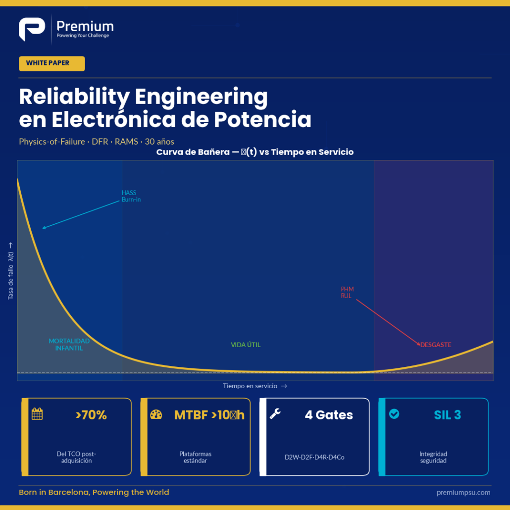
Electronic components exhibit three recognised phases: infant mortality (high initial failure rate from latent manufacturing defects), useful life (low and approximately constant rate), and wear-out (rising rate from accumulation of physical mechanisms). A mature DFR process attacks all three simultaneously.
| Technique | Phase Addressed | When Applied | Premium SA Standard |
|---|---|---|---|
| HALT (Highly Accelerated Life Testing) | Design margin discovery | Design phase on prototypes | Combined temperature + vibration stresses beyond specification limits |
| HASS (Highly Accelerated Stress Screening) | Latent manufacturing defects | Production screening | Stress levels just below operating limit; 100% of production units |
| Burn-in | Infant mortality (left tail) | Post-production, pre-delivery | 4 h per unit at +60 to +80 °C; extendable to 8 h for long-interval programmes (Deutsche Bahn) |
3. RAMS — The Contractual Language of Reliability
RAMS stands for Reliability, Availability, Maintainability, Safety — the four metrics with which a railway operator or grid DSO measure equipment suitability over its useful life. EN 50126 is the framework standard; EN 50128 and EN 50129 cover software and functional safety respectively.
Reliability
R(t) — probability of surviving to time t. Expressed as MTBF = 1/λ for exponential distribution, or by Weibull parameters (β, η) for wear-out phases. Premium SA calculates MTBF by PoF, not by parts-count (MIL-HDBK-217F).
Availability
A = MTBF / (MTBF + MTTR). For a substation converter with MTBF = 500,000 h and MTTR = 4 h: A ≈ 99.9992%. The key lever is not only increasing MTBF but also reducing MTTR.
Maintainability
Design levers: LRU architecture (front access, two captive screws, keyed connectors), built-in telemetry and self-test, RUL (Remaining Useful Life) estimation via PHM, and 40-year spares continuity with quarterly obsolescence review.
Safety — EN 50128 / 50129
SIL (Safety Integrity Level) per IEC 61508. PFD (Probability of Failure on Demand) for standby safety functions. SIL 3–4 requires: redundancy, periodic self-test, MC/DC software coverage metrics, formal methods. Premium SA D4Co-SW methodology aligned with EN 50128.
4. The Premium SA DFR Process — Four Sequential Gates
The Design for Reliability (DFR) methodology — originated at the Center of Reliable Power Electronics (CORPE, Aalborg University) and adopted as an internal standard at Premium SA — structures development in four sequential gates with quantitative exit criteria:
| Gate | Objective | Key Activities | Exit Criterion |
|---|---|---|---|
| D2W (Design to Work) | Functional specification | Mission profile definition, requirements capture, architecture selection | Signed mission profile + functional test pass |
| D2F (Design to Function) | Derating and PoF analysis | Tj_max ≤ 80%, Vop ≤ 80%, thermal simulation, stress analysis | All derating targets met; no RPN > 80 open |
| D4R (Design for Reliability) | FMEA, FTA, HALT | FMEA bottom-up + FTA top-down; HALT protocol; Coffin-Manson solder analysis | RPN > 100 blocked; HALT limits documented; MTBF target verified |
| D4Co (Design for Compliance) | Qualification and FRACAS | HASS production screening; burn-in; EMC pre-compliance; EN 50155/EN 61373 qualification | All certifications obtained; FRACAS activated; customer RAMS deliverables signed |
5. FMEA, FTA and the Analytical Hierarchy
Once derating is established, reliability engineering identifies and mitigates dominant failure modes through three complementary analyses:
- FMEA/FMECA (Failure Mode and Effects Analysis): Bottom-up. RPN = Severity × Occurrence × Detection (1–10 scale). At Premium SA, any RPN >80 triggers a documented action plan; RPN >100 blocks the D4Co gate.
- FTA (Fault Tree Analysis): Top-down. Decomposes boolean combinations (AND/OR gates) that may cause system fault. Quantifies impact of redundancies; allows calculation of system-level MTBF.
- ETA (Event Tree Analysis): Inductive. Models scenarios and responses derived from a single initiating event. Useful for evaluating fault propagation in multi-state systems.
6. Keeping Reliability in Service — PHM, FRACAS and Lean Reliability
PHM — Prognostics and Health Management
The active technical frontier today is the transition from fixed-schedule preventive maintenance towards maintenance based on actual condition. In Premium SA converters:
- Real-time Tj estimation of semiconductors from Vce_sat and current, with case-temperature compensation
- Cumulative power-cycle counting with associated ΔTj, to predict RUL (Remaining Useful Life) by PoF models
- ESR monitoring of capacitors by ripple analysis
- Periodic export of operating data over communication bus to the operator’s supervisor, with P-F (potential-functional) profile
FRACAS — The Continuous-Learning Loop
Failure Reporting, Analysis and Corrective Action System: every field return is analysed at the appropriate level — LRU, board, component — root cause is identified, and the corrective action is propagated to design and production. The consequence is that the population of installed equipment improves over time rather than degrading. The problem detected in unit #150 is prevented in unit #151.
About Premium SA — Premium SA is a Barcelona-based manufacturer of power electronics converters for railway, industrial and energy applications. Founded in 1981, with more than 900 standard product designs and over 40 years of operational experience, Premium SA supplies DC/DC converters, DC/AC inverters, AC/AC frequency converters, battery chargers, rectifiers and UPS systems from 50 W to 72 kW. All products are designed and manufactured at the Premium SA plant in Barcelona, with capability for EN 50155, EN 50121-3-2, EN 45545-2 and EN 61373 certification. Premium SA serves OEMs and system integrators across Europe through direct sales and a network of specialist distributors — ELIPSE (Benelux), Elma Electronic (Switzerland), RELEC Electronics (United Kingdom), DACPOL (Poland and Central Europe) and ANDA-OLSEN (Scandinavia).
Premium SA · Barcelona, Spain · info@premiumpsu.com · +34 932 232 685 · www.premiumpsu.com